Automatic focusing system used for regulating solar condensing lens and focusing method thereof

A solar concentrating and lens adjustment technology, applied in the field of solar thermal power generation, can solve the problems of reducing adjustment accuracy, reducing adjustment efficiency, and high requirements for the concentrating system, achieving the effects of shortening adjustment time, improving adjustment efficiency, and high measurement accuracy

Inactive Publication Date: 2014-09-24
DALIAN GREAT OCEAN NEW ENERGY DEV
View PDF7 Cites 22 Cited by
  • Summary
  • Abstract
  • Description
  • Claims
  • Application Information

AI Technical Summary

Problems solved by technology

[0007] ①. Severely restricted by the weather, since it can only be carried out in the presence of the sun, if it encounters continuous rainy days, the focus cannot be adjusted, resulting in low efficiency
[0008] ② Higher requirements on the concentrating system, and there are potential safety hazards at the same time
Since the angle of the sun changes in real time, during the adjustment process, the concentrating system must be able to track the sun with high precision at all times. If there is an angle deviation, it will directly cause adjustment errors
At the same time, due to the real-time changes of the concentrating system, there are also great potential safety hazards when personnel make adjustments later.
[0009] ③. The quality of the focused spot cannot be judged, and there may be local hot spots
[0011] ①. Due to the far distance of the observation point, the adjustment personnel cannot directl

Method used


Image

  • Automatic focusing system used for regulating solar condensing lens and focusing method thereof
  • Automatic focusing system used for regulating solar condensing lens and focusing method thereof
  • Automatic focusing system used for regulating solar condensing lens and focusing method thereof

Examples


Embodiment Construction

[0036] The technical scheme of the present invention is further described below in conjunction with accompanying drawing and specific embodiment:

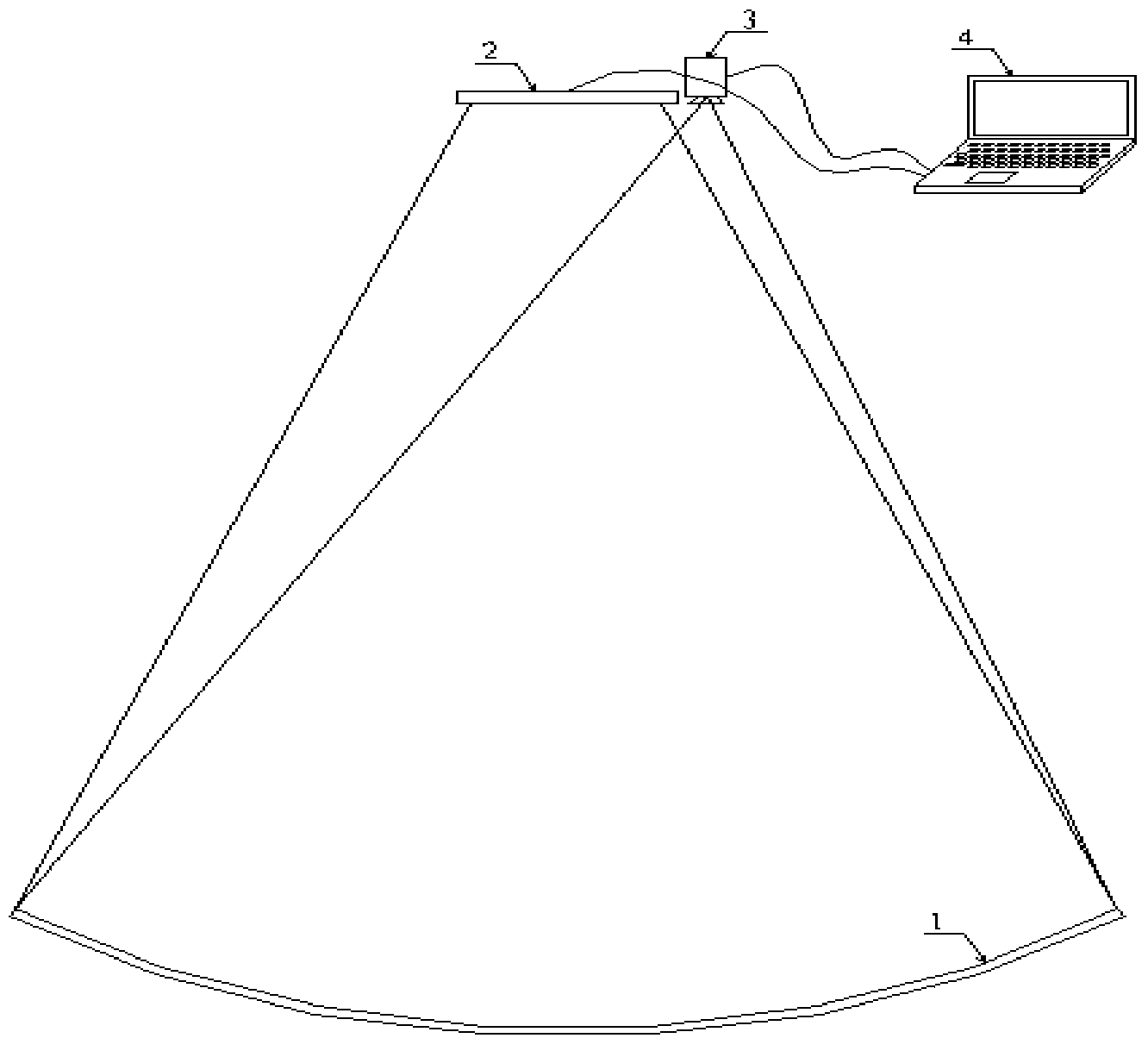
[0037] Such as figure 1 —— Figure 5 shown, according to figure 1 As shown, the image display device 2 and the image acquisition device 3 are placed and fixed in front of the focusing system close to 2 times the focal length. The purpose is to observe the image of the image display device 2 in the focusing system through the image acquisition device 3 . Both the image display device 2 and the image acquisition device 3 are connected to the PC 4 through data lines.

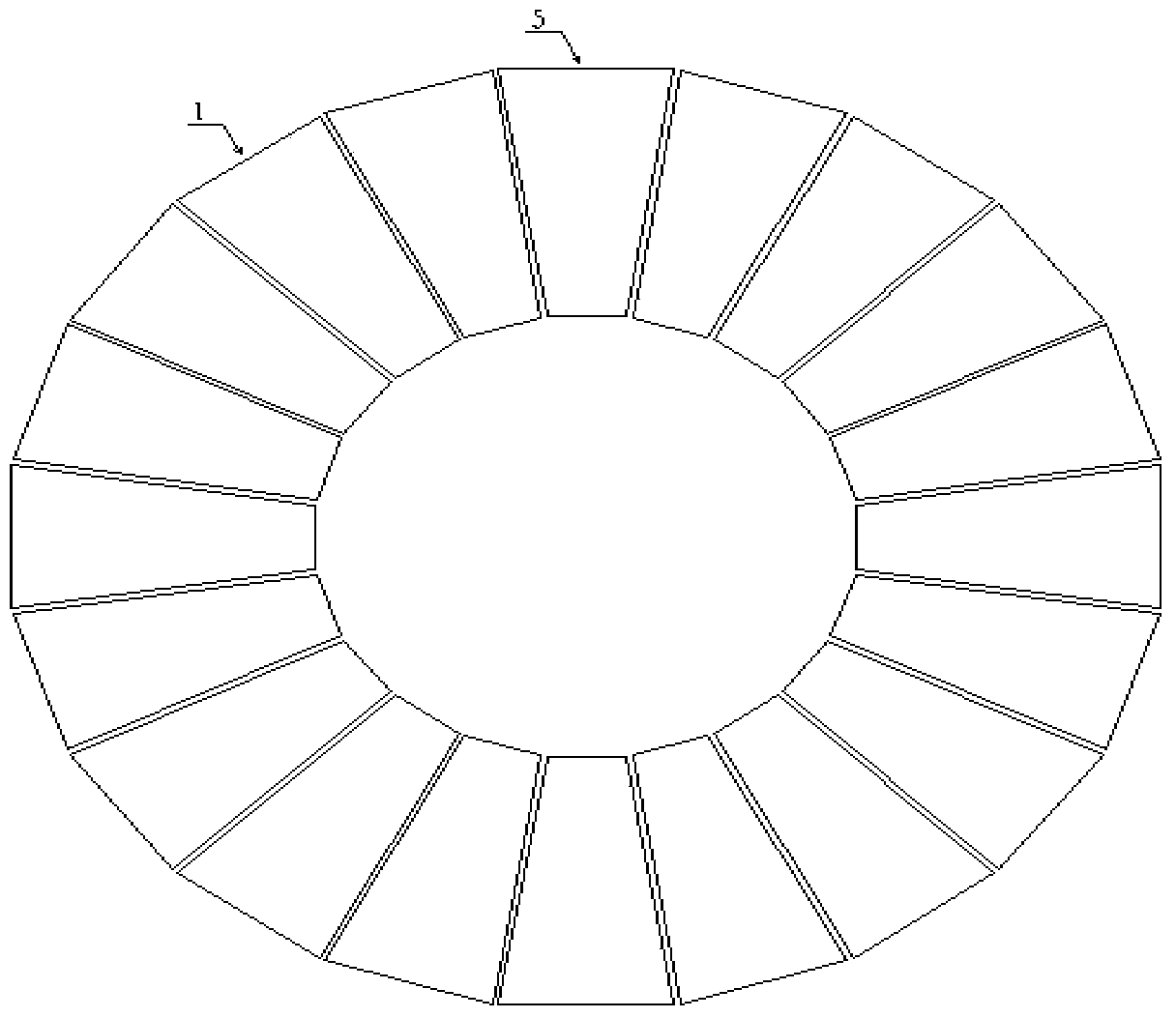
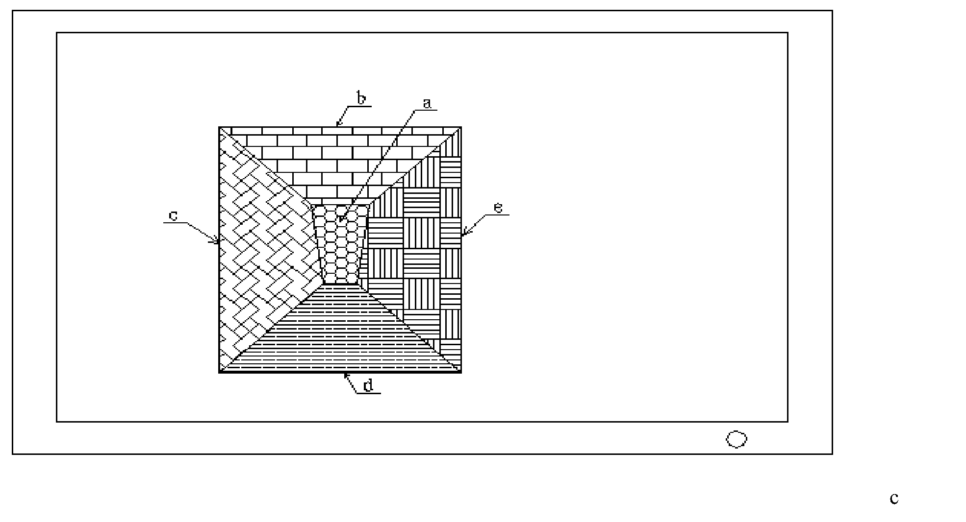
[0038] Such as figure 2 As shown, take a circular concentrating system with 20 reflective lenses in a single circle, and adjust the uppermost reflective lens 5 as an example for illustration, as image 3 As shown, a is the color contour area corresponding to the ideal reflective lens, b is the color area above a, c is the color area to the left of a, d is the color...


PUM


Abstract

The invention discloses an automatic focusing system used for regulating a solar condensing lens and a focusing method of the automatic focusing system. The automatic focusing system comprises image display equipment, image collection equipment and image data processing equipment, wherein the image collection equipment is used for collecting data of images reflected by reflectors; the image display equipment is used for displaying display images which are controlled to be output by the image data processing equipment; the image data processing equipment is used for controlling the image display equipment to output the display images corresponding to region areas of the reflectors of a condensing system in a one-to-one mode, the display image of the region area of any one reflector and display images of region areas on the peripheries of the reflectors are different color images, and the image collection equipment is controlled to perform analysis and processing and output corresponding focusing data after collecting the corresponding images. According to the automatic focusing system, the inclination angle is judged by observing the image colors of the reflectors, the color ratios of discs are calculated and are compared with a pre-stored empirical data base, regulating efficiency is improved substantially, and the regulating time is shortened.

Description

technical field [0001] The invention belongs to the field of solar thermal power generation, and in particular relates to an automatic focusing system and a focusing method for adjusting solar concentrating lenses. Background technique [0002] In the existing field of solar thermal power generation, it mainly includes three types of power generation methods: trough type, tower type, and dish type. The principle is to use concentrating reflective lenses to convert light into heat energy and further convert electric energy. Realize solar power generation. [0003] Since the solar energy itself is relatively scattered, in order to obtain greater energy, a large light-gathering area is required. Due to the limitation of processing and cost, it usually adopts the design method of splicing multiple groups of small reflective lenses into a large curved surface. In the actual assembly process, adjust the angle and position of the small reflective lens so that it can meet the desi...

Claims


Application Information

Patent Timeline
IPC IPC(8): G02B7/183F24J2/10F24S23/70
CPCY02E10/40
Inventor 王振声周改改
Owner DALIAN GREAT OCEAN NEW ENERGY DEV
Why Eureka
Try Eureka