PECVD film deposition equipment and heating plate thereof

A thin film deposition and hot plate technology, which is applied in the manufacture of discharge tubes, electrical components, semiconductors/solid-state devices, etc., can solve problems that affect the online pass rate of process products, waste products and debris, etc., to increase process costs and occupy equipment resources , low cost, simple process to achieve the effect

Inactive Publication Date: 2014-09-24
ADVANCED SEMICON MFG CO LTD
View PDF3 Cites 2 Cited by
  • Summary
  • Abstract
  • Description
  • Claims
  • Application Information

AI Technical Summary

Problems solved by technology

This will cause the wafer to shift (slide) on the surface of the hot plate, and in severe cases, it will cause waste and debris, which affects the online pass rate of process products

Method used


Image

  • PECVD film deposition equipment and heating plate thereof
  • PECVD film deposition equipment and heating plate thereof

Examples


Embodiment Construction

[0020] The present invention will be further described below in conjunction with specific embodiment and accompanying drawing, set forth more details in the following description so as to fully understand the present invention, but the present invention can be implemented in many other modes different from this description obviously, Those skilled in the art can make similar promotions and deductions based on actual application situations without violating the connotation of the present invention, so the content of this specific embodiment should not limit the protection scope of the present invention.

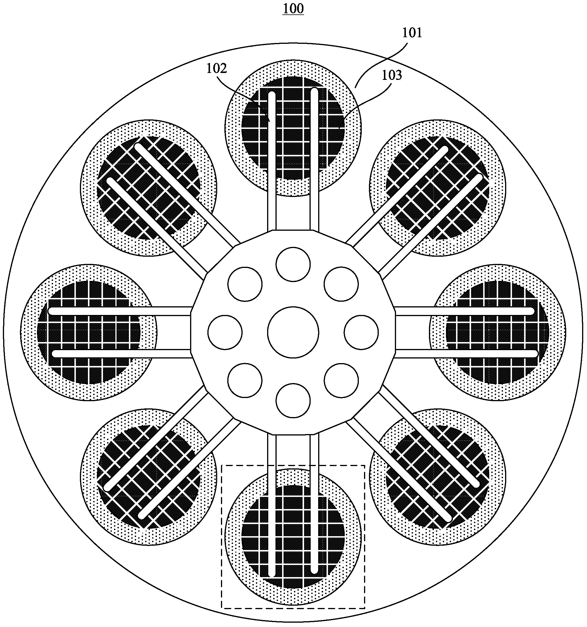
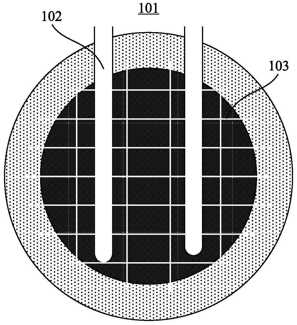
[0021] figure 1 It is a schematic diagram of the overall planar structure of the hot plate of the PECVD film deposition equipment according to one embodiment of the present invention. It should be noted that this and other subsequent drawings are only examples, which are not drawn according to the same scale, and should not be taken as limitations on the protection scope of th...


PUM

PropertyMeasurementUnit
widthaaaaaaaaaa
depthaaaaaaaaaa

Abstract

The invention provides PECVD film deposition equipment and a heating plate thereof. The heating plate is located in a process cavity of the equipment. Eight process positions are uniformly distributed on the heating plate. A wafer at each process position is passed to the next adjacent process position through rotation of an aluminum fork. A plurality of venting marks penetrating through a process area are distributed on each process position of the heating plate. According to the equipment and the heating plate, after the wafers are placed on the surface of the heating plate of the equipment, gas can be uniformly exhausted towards the periphery through the venting marks, and therefore slipping of the wafer due to the air cushion effect can be avoided.

Description

technical field [0001] The invention relates to the technical field of semiconductor manufacturing equipment, in particular, the invention relates to a PECVD film deposition equipment and a hot plate thereof. Background technique [0002] In the film deposition process, if a certain film (such as TEOS, etc.) has been grown on the back of the wafer, the gas adsorbed on the film cannot be completely removed in the subsequent annealing process, or placed in a normal temperature environment , the film re-adsorbs the gas, causing the wafer to concentrate a large amount of outgassing on the hot plate of the cavity placed in a vacuum of 400 degrees, forming an air cushion effect. This will cause the wafer to shift (slide) on the surface of the hot plate, and in severe cases, it will cause waste and debris, which affects the online qualification rate of process products. Contents of the invention [0003] The technical problem to be solved by the present invention is to provide a...

Claims


Application Information

Patent Timeline
Patent Type & Authority Applications(China)
IPC IPC(8): H01L21/314C23C16/513
CPCH01J37/32449C23C16/513
Inventor 梁建雄周冰
Owner ADVANCED SEMICON MFG CO LTD
Why Eureka
Try Eureka