FPGA (Field Programmable Gate Array) based electroencephalogram and electro-oculogram signal analysis method and system

An electro-ophthalmic signal and analysis method technology, applied in the field of signal analysis, can solve problems such as inability to meet online processing requirements, difficult industrialization implementation, poor portability, etc., achieve high flexibility and high-speed parallel computing, improve processing speed, and reduce hardware. cost effect

Active Publication Date: 2014-10-01
GUANGZHOU INST OF ADVANCED TECH CHINESE ACAD OF SCI
View PDF4 Cites 4 Cited by
  • Summary
  • Abstract
  • Description
  • Claims
  • Application Information

AI Technical Summary

Problems solved by technology

The disadvantage is that due to the limitation of computing speed, it cannot meet the online processing requirements for large-scale EEG and oculoelectric signals, and is often used in the occasion of offline analysis and processing of signals; the hardware method mostly uses high-performance computers as the main processing unit, and the advantage is that it can Meet the online processi

Method used


Image

  • FPGA (Field Programmable Gate Array) based electroencephalogram and electro-oculogram signal analysis method and system
  • FPGA (Field Programmable Gate Array) based electroencephalogram and electro-oculogram signal analysis method and system
  • FPGA (Field Programmable Gate Array) based electroencephalogram and electro-oculogram signal analysis method and system

Examples


Embodiment Construction

[0035] The specific embodiment of the present invention will be further described below in conjunction with accompanying drawing:

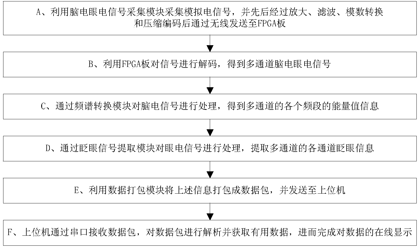
[0036] refer to figure 1 , the inventive method comprises the following steps:

[0037] A. Use the EEG signal acquisition module to collect analog electrical signals, and send them to the FPGA board through wireless after successively amplifying, filtering, analog-to-digital conversion and compression coding;

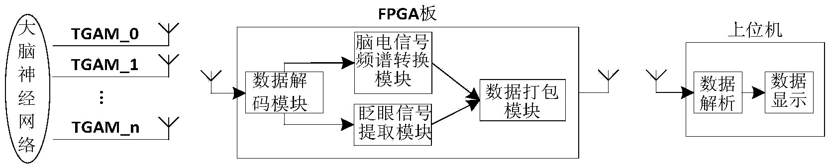
[0038] A single TGAM module is used as a single EEG signal acquisition module, refer to figure 2 , the TGAM data acquisition module of the present invention is jointly formed by a plurality of TGAM_x.

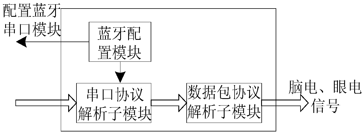
[0039] In this embodiment, the TGAM data acquisition module transmits data to the Bluetooth serial port module through the Bluetooth wireless communication protocol, and the Bluetooth serial port module converts the received data into a serial port protocol standard, and finally transmits the data to the FPGA module.

[0040] B. Use the ...


PUM


Abstract

The invention discloses an FPGA (Field Programmable Gate Array) based electroencephalogram and electro-oculogram signal analysis method and system. The FPGA based electroencephalogram and electro-oculogram signal analysis method comprises collecting electric signals on the surface of the cerebral cortex through a signal collection module and enabling the electric signals to be converted into digital signals and transmitted to an FPGA board in a wireless transmission mode for decoding; obtaining different frequency bands of energy intensities of electroencephalogram signals through a spectrum conversion module; obtaining the blinking intensity of electro-oculogram signals through a blinking signal extraction module; performing data packaging on the electroencephalogram and electro-oculogram signals after processing and transmitting a data package to an upper computer in a wireless mode; performing resolution on the data package through the upper computer and performing real-time display on the useful information. According to the FPGA based electroencephalogram and electro-oculogram signal analysis method and system, the processing speed of data is improved through the multi-channel electroencephalogram signal spectrum conversion and blinking signal extraction; the accuracy and the transmission efficiency of the data are ensured through the data packaging, the low-cost online processing on the large-scale electroencephalogram and electro-oculogram signals is implemented, and the embedded implementation is easy to achieve; the FPGA based electroencephalogram and electro-oculogram signal analysis method and system can be widely applied to the signal analysis field.

Description

technical field [0001] The invention relates to the field of signal analysis, in particular to an FPGA-based electroencephalogram signal analysis method and system. Background technique [0002] In recent years, human-computer interaction technology using bioelectrical signals such as EEG and oculoelectric signals as information carriers is an important research direction in the field of computer applications and information processing. It has important scientific significance and broad application prospects. However, when the number of bioelectrical signal channels is large and the amount of information is large, how to ensure the online analysis and processing of large-scale signals has become an urgent problem to be solved. [0003] The traditional large-scale EEG and OEG signal analysis and processing methods can be divided into two categories: software and hardware methods. The software method has the advantages of low cost and simple operation. The disadvantage is tha...

Claims


Application Information

Patent Timeline
IPC IPC(8): A61B5/0476A61B5/0496
Inventor 夏效禹麦穗冬潘文明王腾飞王小航严锡裕
Owner GUANGZHOU INST OF ADVANCED TECH CHINESE ACAD OF SCI
Why Eureka
Try Eureka