Boiler combustion test furnace

A boiler combustion and combustion test technology, applied to measuring devices, instruments, etc., can solve the problems of many heating surfaces and the inability to simulate power station combustion, etc., and achieve the effect of environmental friendliness, environmental protection and large-scale

Inactive Publication Date: 2014-10-01
SHANGHAI HEAT ENERGY TECH
View PDF9 Cites 3 Cited by
  • Summary
  • Abstract
  • Description
  • Claims
  • Application Information

AI Technical Summary

Problems solved by technology

However, since the size of the test furnace is much smaller than the actual boiler, the pure water-cooled wall structure of the boiler is directly used, resulting in too many heating surfaces, which cannot simulate the actual combustion of the power station.

Method used


Image

  • Boiler combustion test furnace
  • Boiler combustion test furnace
  • Boiler combustion test furnace

Examples


Embodiment Construction

[0024] Specific embodiments of the present invention are described in detail below, and the present embodiment is carried out under the premise of the present invention, has provided detailed implementation and specific operation process, but protection scope of the present invention is not limited to following embodiment .

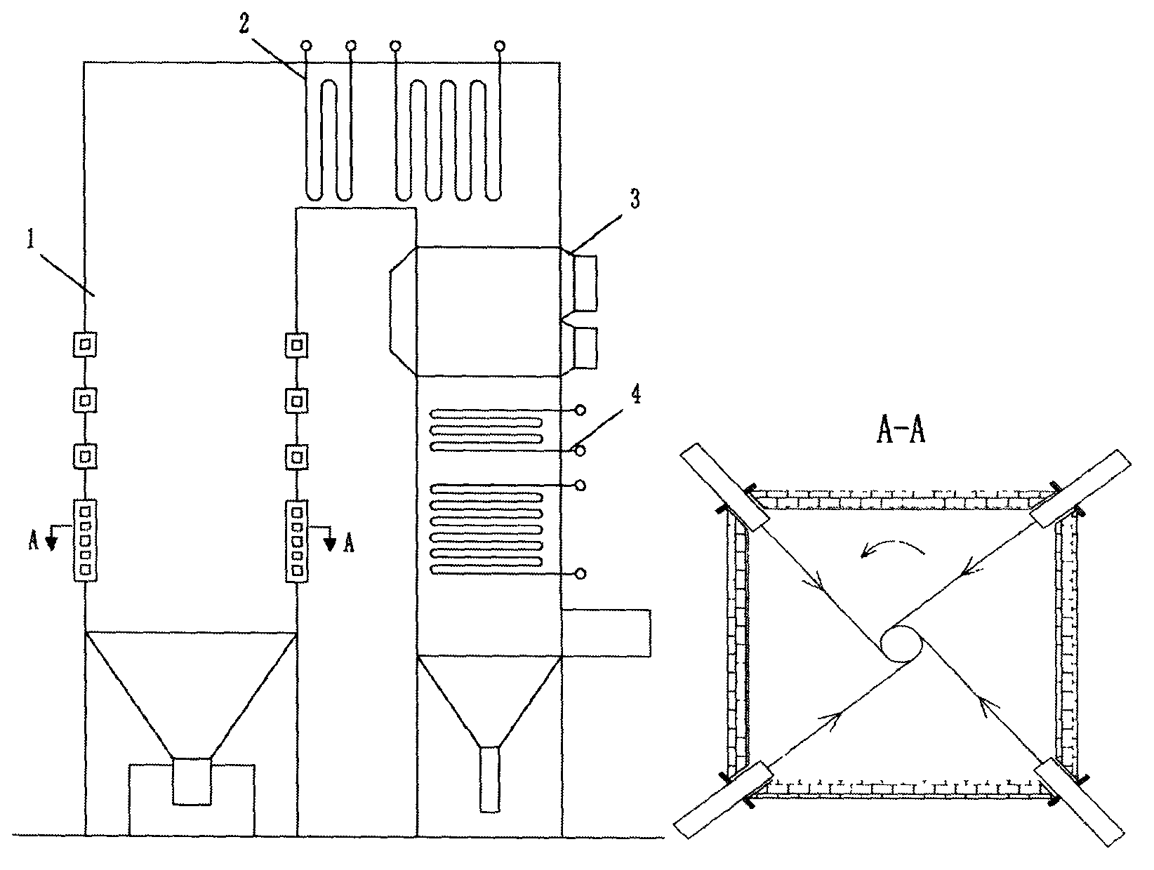
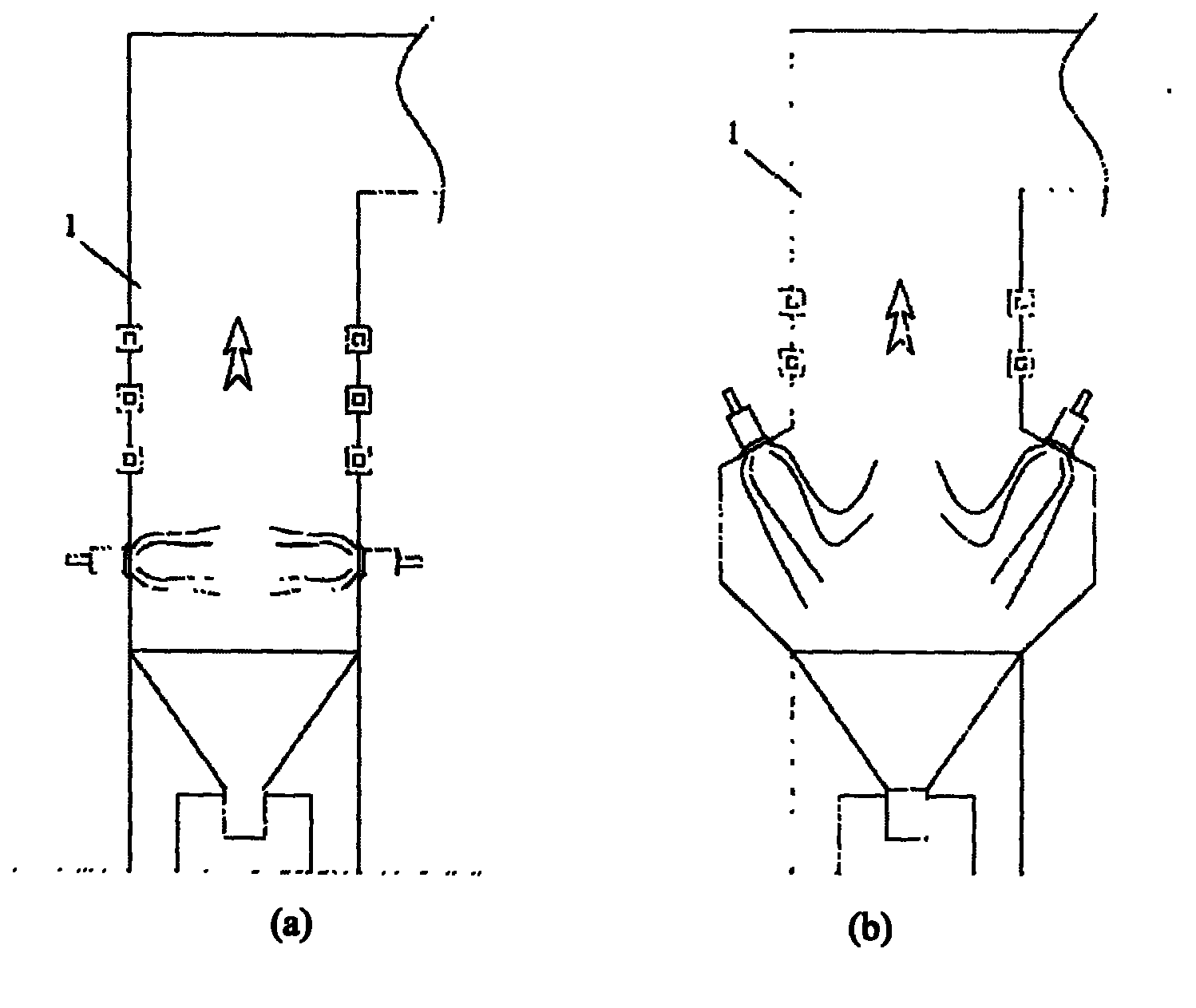
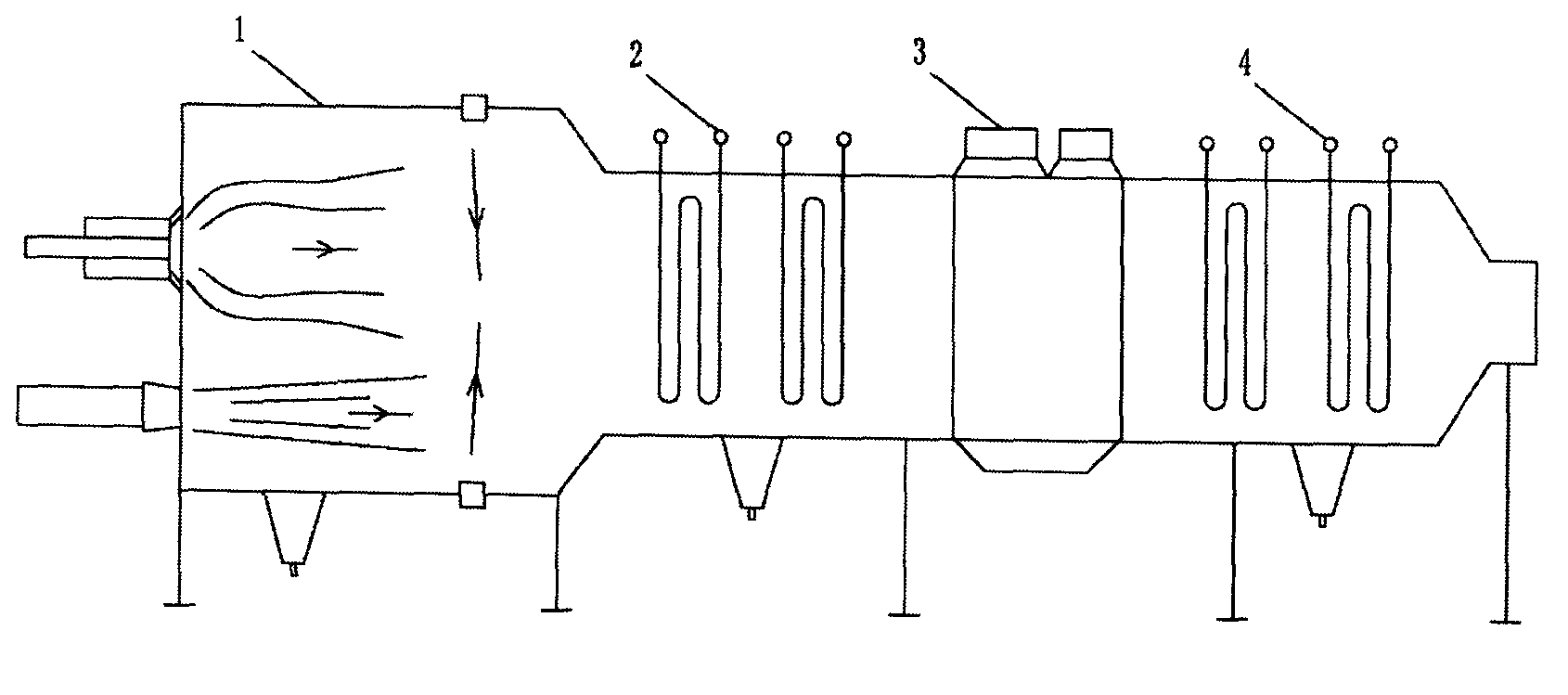
[0025] Such as Figure 4 As shown, this embodiment includes: interval furnace 1, removable graded high-temperature convection heating surface 2, high-temperature air preheater 3, graded low-temperature economizer 4, combustion medium 5, and other structures 6.

[0026] The spaced furnace 1 includes: a heat-resistant furnace wall 101, a water-cooled furnace wall 102, and a supporting furnace roof 103, wherein: the heat-resistant furnace wall 101 and the water-cooled furnace wall 102 are arranged in layers and at intervals, and the supporting furnace roof is supported by water-cooled support tubes. Hot furnace wall composition.

[0027] The detachable and...


PUM

PropertyMeasurementUnit
Heat resistance temperatureaaaaaaaaaa

Abstract

A boiler combustion test furnace is characterized by comprising an interval hearth, a removable classified high-temperature convective heating surface, a high-temperature air pre-heater, and a classified low-temperature coal-saved device. The boiler combustion test furnace provided by the invention creates a test condition of simulating actual power plant boiler combustion for the advanced combustion technology.

Description

technical field [0001] The invention relates to a device in the field of boiler combustion tests, in particular to a boiler combustion test furnace. Background technique [0002] With the continuous improvement of the country's environmental protection requirements, combustion technology also needs continuous innovation and upgrading. The research and development of new technologies is inseparable from effective test equipment. Large foreign combustion technology companies usually have their own corresponding test equipment. In China, there is no corresponding test equipment. In order to develop a series of advanced combustion technologies, it is necessary to have equipment capable of simulating actual combustion such as power plant boilers. [0003] After investigating a large number of related patents, scientific research documents and combustion equipment manufacturers, it is found that the current domestic combustion tests mainly have the following phenomena: First, a...

Claims


Application Information

Patent Timeline
IPC IPC(8): G01D21/00
Inventor 李友谊孙长江麻泰留耿亮
Owner SHANGHAI HEAT ENERGY TECH
Why Eureka
Try Eureka