Online detection device for variation of metal melt structure caused by ultrasonic preprocessing

An ultrasonic pretreatment, metal melt technology, applied in the field of material science, can solve the problems of long test cycle, discontinuity, hysteresis of pretreatment effect, etc., to facilitate insertion and withdrawal, improve repeatability, and ensure temperature consistency Effect

Active Publication Date: 2014-10-01
NORTHEASTERN UNIV
View PDF5 Cites 5 Cited by
  • Summary
  • Abstract
  • Description
  • Claims
  • Application Information

AI Technical Summary

Problems solved by technology

The problem is that there is hysteresis and discontinuity in the investigation of the pretreatment effect, that is, the test period is long, and it is impossible to conduct a full inspection of the pretreatment process
However, due to the mutual interference between the alternating magnetic field used for detection and the ultrasound and its mechanism, the indirect method cannot realize the accurate detection of the resistance change of the metal melt caused by the ultrasound, and the introduction of the ultrasound in the metal melt often uses a metal ultrasonic rod. The electrode method cannot rule out the interference caused by the conduction of the ultrasonic rod

Method used


Image

  • Online detection device for variation of metal melt structure caused by ultrasonic preprocessing
  • Online detection device for variation of metal melt structure caused by ultrasonic preprocessing
  • Online detection device for variation of metal melt structure caused by ultrasonic preprocessing

Examples


Embodiment 1

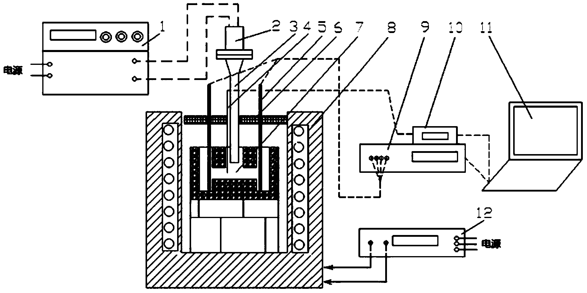
[0074] (1) Insert the measuring electrode into the electrode insertion hole along the reserved hole on the upper cover of the resistance heating and holding furnace until the electrode touches the bottom of the electrode insertion hole and fix it, and connect the detection circuit;

[0075] Insert the temperature measuring thermocouple from the insertion hole of the ultrasonic horn into the center of the horizontal hole and fix it;

[0076] Insert the ultrasonic amplitude-changing introduction rod into the metal melt storage unit through the insertion hole of the ultrasonic amplitude-changing introduction rod, and place it above the horizontally arranged circular hole;

[0077] Preheat the resistance heating holding furnace to the melting temperature of Pb-20wt.%Sn, open the upper cover of the holding furnace, pour the alloy melt preheated to 150°C above the liquidus line into the metal melt storage unit until the metal When the melt level reaches 10mm from the upper opening o...

Embodiment 2

[0082] (1) Insert the measuring electrode into the electrode insertion hole along the reserved hole on the upper cover of the resistance heating and holding furnace until the electrode touches the bottom of the electrode insertion hole and fix it, and connect the detection circuit;

[0083] Insert the temperature measuring thermocouple from the insertion hole of the ultrasonic horn into the center of the horizontal hole and fix it;

[0084] Insert the ultrasonic amplitude-changing introduction rod into the metal melt storage unit through the insertion hole of the ultrasonic amplitude-changing introduction rod, and place it above the horizontally arranged circular hole;

[0085] Preheat the resistance heating holding furnace to the melting temperature of Pb-20wt.%Sn, open the upper cover of the holding furnace, pour the alloy melt preheated to 150°C above the liquidus line into the metal melt storage unit until the metal When the melt level reaches 10mm from the upper opening o...

Embodiment 3

[0090] (1) Insert the measuring electrode into the electrode insertion hole along the reserved hole on the upper cover of the resistance heating and holding furnace until the electrode touches the bottom of the electrode insertion hole and fix it, and connect the detection circuit;

[0091] Insert the temperature measuring thermocouple from the insertion hole of the ultrasonic horn into the center of the horizontal hole and fix it;

[0092] Insert the ultrasonic amplitude-changing introduction rod into the metal melt storage unit through the insertion hole of the ultrasonic amplitude-changing introduction rod, and place it above the horizontally arranged circular hole;

[0093] Preheat the resistance heating holding furnace to the melting temperature of Pb-20wt.%Sn, open the upper cover of the holding furnace, and pour the alloy melt preheated to 150°C above the liquidus line into the metal melt storage unit until the metal When the melt level reaches 10mm from the upper openi...


PUM


Abstract

The invention belongs to the technical field of the material science, and particularly relates to an online detection device for variation of a metal melt structure caused by the ultrasonic preprocessing. The detection device comprises a heating heat preserving system, a metal melt storage unit, a power ultrasonic system, a melt resistor or a resistivity detection system, a melt temperature signal collection system, a data collection and processing system and the like. By adopting the detection device, the metal melt structure variation caused by the ultrasonic can be detected and represented by utilizing a variable quantity delta r of physical parameters-resistance parameters of structure sensitivity, so that the insulation problem of a power ultrasonic lead-in pole can be successfully solved, the influence on an ultrasonic bar caused by utilizing a voltammetry to measure the resistance of ultrasonic metal melt can be overcome, the real-time, synchronous, continuous and high-precision automatic collection and processing of the resistance and temperature data can be realized by utilizing the advanced electronic measurement technology and computer technology, and the precise measurement can be realized by adopting a double-electrode method and a four-electrode method.

Description

technical field [0001] The invention belongs to the technical field of material science, and in particular relates to an on-line detection device for the structure change of metal melt caused by ultrasonic pretreatment. Background technique [0002] The key to controlling the solidification behavior is to control the nucleation process of the metal melt. All methods that can increase the nucleation rate can achieve the refinement of the solidification structure. Melt pretreatment can change the melt structure and increase the nucleation rate, so it is a common method to achieve as-cast microstructure refinement. External field pretreatment refinement of metal melt is a process method to promote homogeneous nucleation to achieve refinement. One of its mechanisms is to increase the nucleation rate by changing the dynamic fluctuation equilibrium state of the melt structure, that is, the application of an external field The short-range ordered structure of the metal melt is ch...

Claims


Application Information

Patent Timeline
Patent Type & Authority Applications(China)
IPC IPC(8): G01N27/04
Inventor 乐启炽张建锋刘轩胡文义张志强崔建忠
Owner NORTHEASTERN UNIV
Why Eureka
Try Eureka