
Rader receiving system

A technology of receiving system and radar, applied in the field of electronic technology application, can solve the problem that omnidirectional situational target monitoring cannot be realized, and achieve the effect of expanding dynamic

Inactive Publication Date: 2014-10-01
XIAN TIANHE DEFENCE TECH
View PDF6 Cites 5 Cited by
  • Summary
  • Abstract
  • Description
  • Claims
  • Application Information

AI Technical Summary

Problems solved by technology

Beam mechanical scanning is to form a full range of beam scanning by driving the antenna to rotate through the azimuth servo mechanism, and then the echo signal in the corresponding azimuth is sent to the receiver for processing, which cannot realize omnidirectional situational target monitoring; beam electronic scanning is through multiple sets of electronic scanning. The switch switches the transmitted signal to the antenna in the corresponding azimuth according to a certain timing, and at the same time the receiver obtains the target echo in this azimuth for processing, and it cannot realize omnidirectional situational target monitoring

Method used


Image

  • Rader receiving system
  • Rader receiving system
  • Rader receiving system

Examples


Embodiment

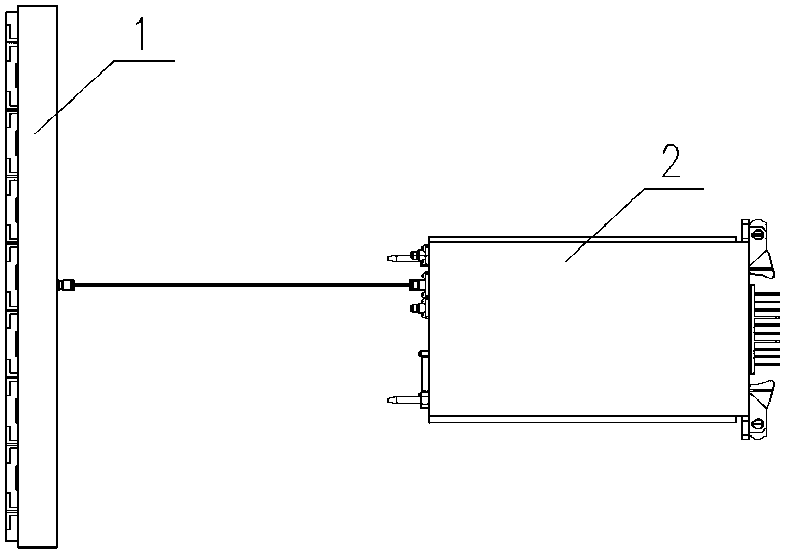
[0034] The receiver of this embodiment is composed of 72 receiver subunits to form a cylinder combination receiver, and each receiver subunit is formed as figure 1 As shown, it consists of a dielectric microstrip antenna 1 and a receiver 2 .

[0035] Such as Image 6 with Figure 7 As shown, the receiving antenna is integrally connected by upper and lower mounting plates and 72 microstrip antennas 1, which can ensure the strength of the antenna. The upper and lower mounting plates are processed by a whole piece of aluminum plate. There are 72 antenna mounting slots on the mounting plate. The angle accuracy between adjacent mounting slots can be controlled at 0.02°, which can ensure the angle of 5°±0.1° between the two antennas. precision requirements.

[0036] 72 dielectric microstrip antennas 1 and 72 receivers 2 are processed and produced in the same batch to ensure consistency.

[0037] The dielectric microstrip antenna 1 in this embodiment is vertically polarized, with...


PUM


Abstract

The invention discloses a radar receiving system. The radar receiving system comprises a plurality of receiver sub-units. A cylindrical surface receiving array is formed by the receiver sub-units. Each receiver sub-unit comprises a microstrip antenna and a receiver. All-direction receiving beams are formed through the receiver array mode. Azimuth angles are measured by the adoption of an amplitude comparison angle measurement technology, and then all-direction situation monitoring of a target is achieved. Due to the fact that each receiver sub-unit is composed of the dielectric microstrip antenna and the receiver, the perpendicular polarization mode is adopted in the dielectric microstrip antennas, the superheterodyne mode is adopted in the receivers, the receiver in each receiver sub-unit is mainly composed of an amplitude limiting low noise amplifier, an image rejection frequency mixer, an MGC control circuit, an intermediate-frequency amplification and matching filter and the like, and the receivers in the receiver sub-units are completely consistent in index requirement during one-time down-conversion to intermediate frequency.

Description

technical field [0001] The invention belongs to the application field of electronic technology, and relates to a radar receiver, in particular to a cylinder combined array radar receiver. Background technique [0002] At present, most radar beam scanning adopts mechanical scanning or electronic scanning. Beam mechanical scanning is to form a full range of beam scanning by driving the antenna to rotate through the azimuth servo mechanism, and then the echo signal in the corresponding azimuth is sent to the receiver for processing, which cannot realize omnidirectional situational target monitoring; beam electronic scanning is through multiple sets of electronic scanning. The switch switches the transmitting signal to the antenna in the corresponding azimuth according to a certain timing, and at the same time, the receiver obtains the target echo in this azimuth for processing, and it cannot realize omnidirectional situational target monitoring. Contents of the invention [...

Claims


Application Information

Patent Timeline
Patent Type & Authority Applications(China)
IPC IPC(8): G01S7/285G01S7/34G01S7/35
CPCG01S7/285G01S7/34G01S7/354
Inventor 杨永锋刘升华
Owner XIAN TIANHE DEFENCE TECH
Learn More