Astigmatic deformable mirror device

A technology of deformable mirror and astigmatism, which is applied in the field of system aberration compensation, can solve the problems of difficult manufacturing and large rigid body displacement, and achieve the effects of reducing rigid body displacement, simplifying device structure, and increasing deformation capacity

Inactive Publication Date: 2014-10-01
CHANGCHUN INST OF OPTICS FINE MECHANICS & PHYSICS CHINESE ACAD OF SCI
View PDF7 Cites 2 Cited by
  • Summary
  • Abstract
  • Description
  • Claims
  • Application Information

AI Technical Summary

Problems solved by technology

[0006] The purpose of the present invention is to propose an astigmatic deformable mirror device, which solves the problems of processing and manufacturing difficulties and introducing large displacements of rigid bodies in the prior art

Method used


Image

  • Astigmatic deformable mirror device
  • Astigmatic deformable mirror device
  • Astigmatic deformable mirror device

Examples


Embodiment Construction

[0018] Embodiments of the present invention will be further described below in conjunction with the accompanying drawings.

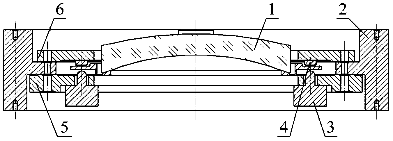
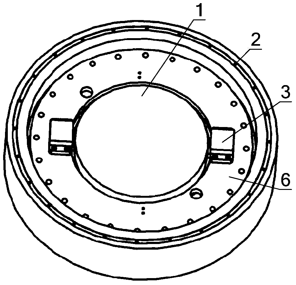
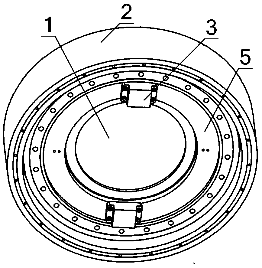
[0019] See attached figure 1 , attached figure 2 And attached image 3 , an astigmatic deformable mirror device of the present invention includes an optical element 1, a deformable mirror frame 2, four actuators 3, four displacement sensors 4, an upper fixed plate 6 and a lower fixed plate 5;

[0020] The optical element 1 and the deformable frame 2 form a frame assembly by gluing or pressing, the upper fixing plate 6 and the lower fixing plate 5 are respectively fixed on the deformable frame 2 by screws, and the upper fixing The plate 6 is provided with two actuators 3 distributed at 180° in the circumferential direction to push the deformable mirror frame 2 downward, and the lower fixed plate 5 is provided with two actuators 3 distributed at 180° in the circumferential direction and pushed upward The deformable mirror frame 2, the four actuators 3 ...


PUM


Abstract

The invention relates to an astigmatic deformable mirror device, which belongs to the field of system aberration compensation of an optical system and aims to solve the problems of difficulty in processing and manufacturing and large displacement of an introduced rigid body in the prior art. The astigmatic deformable mirror device comprises an optical element, a deformable mirror frame, four actuators, four displacement sensors, an upper fixed plate and a lower fixed plate, wherein the optical element and the deformable mirror frame are connected into a mirror frame assembly in a gluing or compressing mode; the upper fixed plate and the lower fixed plate are fixed on the deformable mirror frame respectively by screws; two actuators which are circumferentially distributed in 180 degrees are arranged on the upper fixed plate, the other two actuators which are circumferentially distributed in 180 degrees are arranged on the lower fixed plate, the four actuators on the upper fixed plate and the lower fixed plate are circumferentially distributed in 90 degrees, the actuators are arranged along the direction of an optical axis of the optical element, and input displacements vertically act on the deformable mirror frame; and the four displacement sensors are respectively arranged on the upper fixed plate and the lower fixed plate and are opposite to the four actuators.

Description

technical field [0001] The invention belongs to the field of system aberration compensation of an optical system, in particular to the system aberration compensation in a lithographic projection objective lens system, and in particular relates to an astigmatic deformation mirror device capable of causing astigmatic deformation of an optical element. Background technique [0002] For the manufacturing process of large-scale integrated circuits, projection lithography is the most critical process, which requires the use of projection lithography machines, and the projection objective lens is the core of projection lithography machines, and its performance directly determines the graphics transfer of lithography ability. [0003] The optical elements in the projection objective lens system, especially the illumination areas of the optical elements near the silicon wafer and the mask, are rotationally asymmetric, resulting in a non-rotationally symmetric temperature gradient in ...

Claims


Application Information

Patent Timeline
Patent Type & Authority Applications(China)
IPC IPC(8): G03F7/20G02B7/02
Inventor 赵磊刘震宇谢军杨怀江隋永新张巍
Owner CHANGCHUN INST OF OPTICS FINE MECHANICS & PHYSICS CHINESE ACAD OF SCI
Why Eureka
Try Eureka