
Active EMI filter and power management device

A filter and power line technology, applied in the electronic field, can solve problems such as signal distortion, complex noise signal components, and amplification circuit distortion, and achieve the effects of preventing distortion, improving performance and reliability, and avoiding electromagnetic interference

Active Publication Date: 2014-10-01
HUAWEI TECH CO LTD
View PDF3 Cites 12 Cited by
  • Summary
  • Abstract
  • Description
  • Claims
  • Application Information

AI Technical Summary

Problems solved by technology

Usually the input differential circuit of the voltage-current conversion circuit cannot be completely symmetrical, and there is an offset voltage
However, in a general active EMI filter, the current injection circuit is a DC blocking circuit. When the AC input is zero, the output signal of the voltage-current conversion circuit will have nothing to do with the current injection circuit, but is determined by the offset voltage. At this time, the voltage- The static operating point of the current conversion circuit will shift, resulting in distortion of the amplification circuit
In addition, the composition of the noise signal is very complex and may contain a small amount of transient DC components. If these DC components are not processed, the signal output by the amplifier circuit will be distorted.
The distortion of the amplifier circuit will greatly reduce the performance of the active EMI filter, and even cause the active EMI filter to fail to work properly.

Method used


Image

  • Active EMI filter and power management device
  • Active EMI filter and power management device
  • Active EMI filter and power management device

Examples


Embodiment Construction

[0034]The following will clearly and completely describe the technical solutions in the embodiments of the present invention with reference to the accompanying drawings in the embodiments of the present invention. Obviously, the described embodiments are only some, not all, embodiments of the present invention. Based on the embodiments of the present invention, all other embodiments obtained by persons of ordinary skill in the art without creative efforts fall within the protection scope of the present invention.

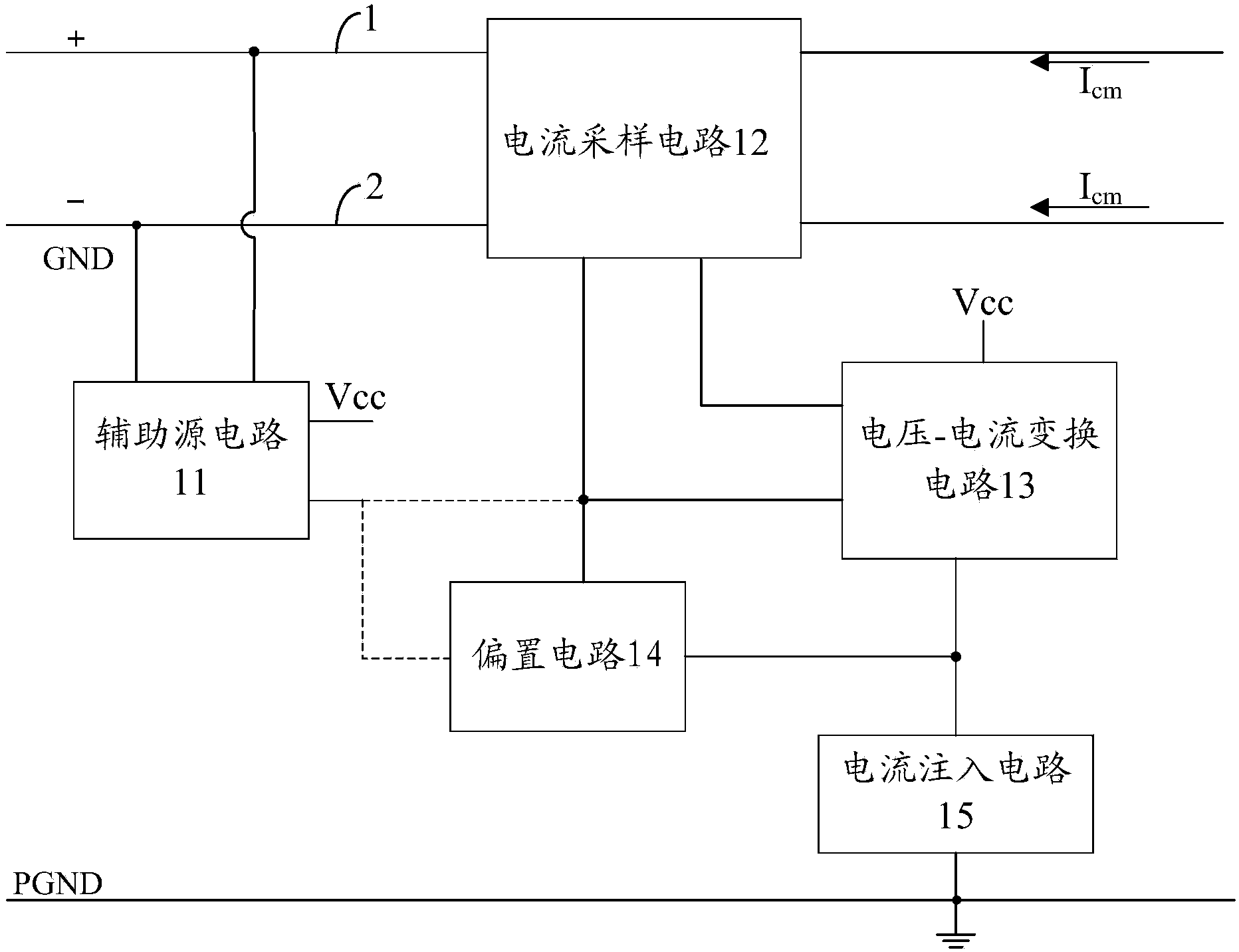
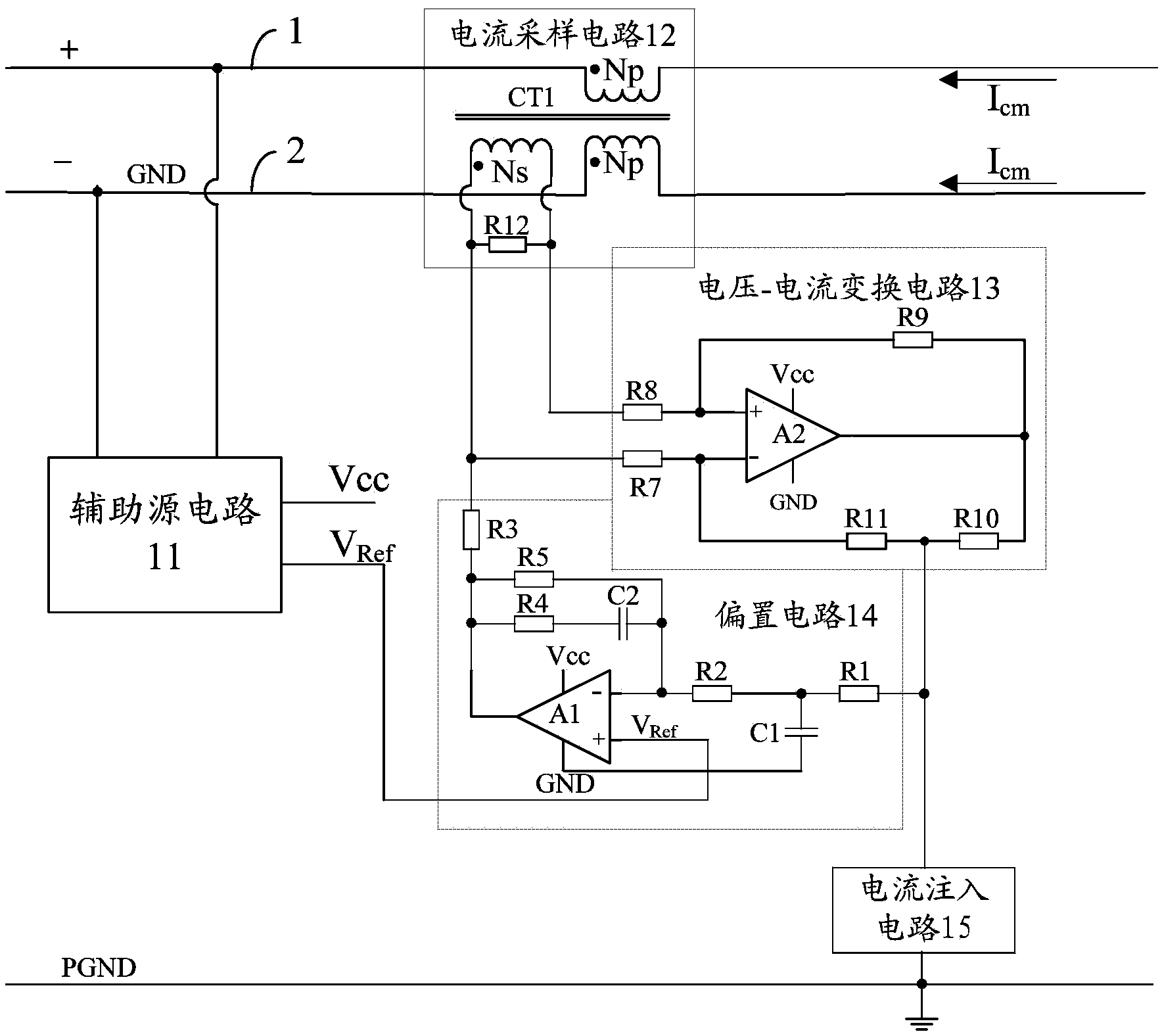
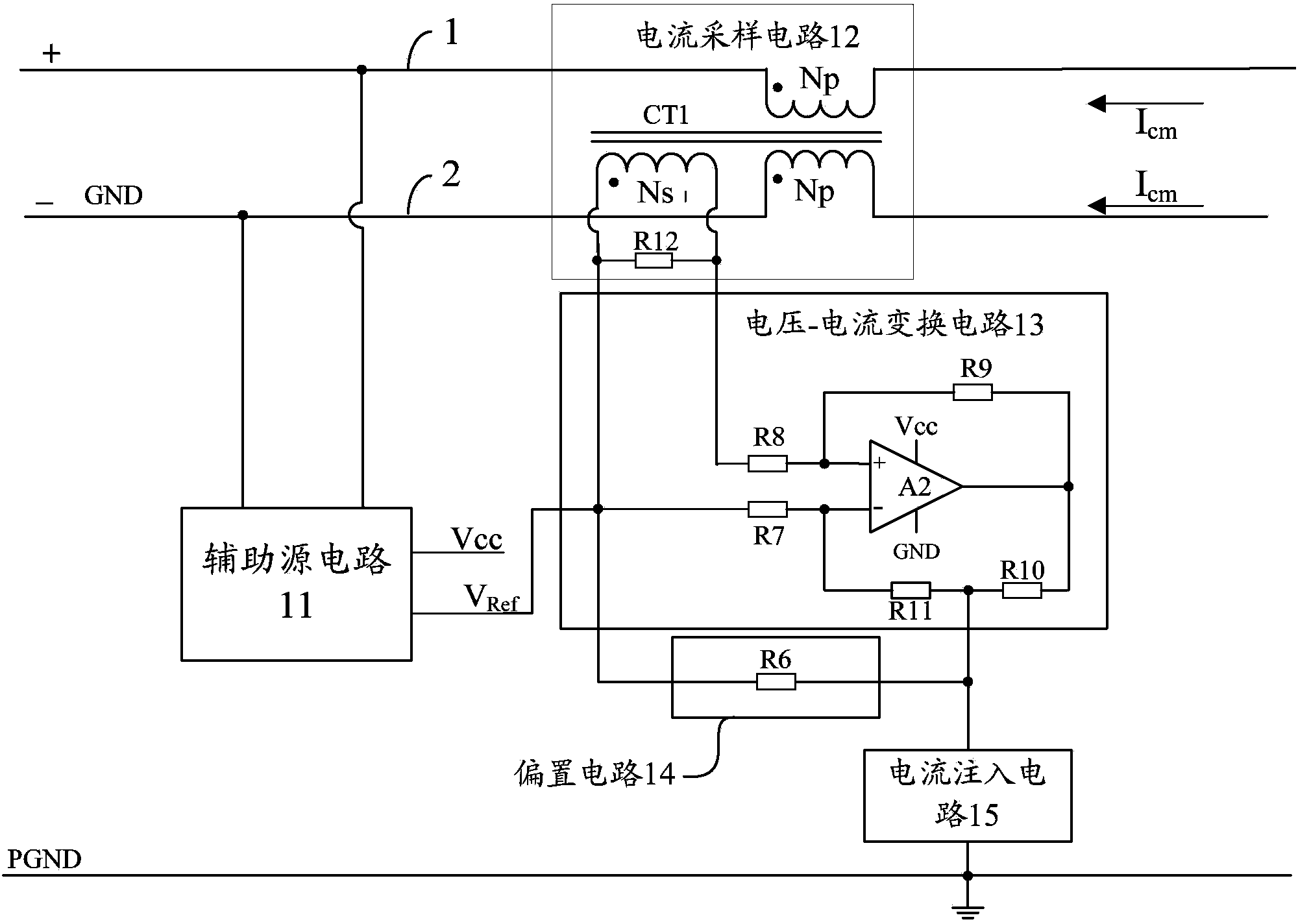
[0035] see figure 1 , is a schematic structural diagram of an embodiment of the active EMI filter provided by the present invention, wherein the dotted line indicates a possible connection mode. like figure 1 As shown, the active EMI filter may include an auxiliary source circuit 11, a current sampling circuit 12, a voltage-current conversion circuit 13 and a current injection circuit 14, wherein:

[0036] The first input end and the second input end of the auxili...


PUM


Abstract

The embodiment of the invention discloses an active EMI filter and a power management device. The active EMI filter comprises an auxiliary source circuit, a current sampling circuit, a voltage-current conversion circuit, a biasing circuit and a current injection circuit. The auxiliary source circuit is used for conducting voltage stabilizing on voltage signals obtained from a power line and outputting the voltage signals which receive voltage stabilizing processing to other circuits for power supply, and common-mode noise currents sequentially pass through the current sampling circuit, the voltage-current conversion circuit and the current injection circuit and are finally injected to a protected area. The biasing circuit can compensate for input signals of the voltage-current conversion circuit according to current signals output by the voltage-current conversion circuit and provide a correct static working point for the voltage-current conversion circuit. According to the active EMI filter and the power management device, distortion of the active EMI filter can be prevented, and the performance and reliability of the active EMI filter are improved.

Description

technical field [0001] The invention relates to the field of electronic technology, in particular to an active EMI filter and a power management device. Background technique [0002] With the extensive application of electrical and electronic equipment, the problem of Electromagnetic Interference (EMI) is becoming more and more serious. In order to filter out the EMI signal on the wire, an active EMI filter is generally added to the circuit system. [0003] Commonly used active EMI filters usually use the voltage-current conversion circuit to process the voltage-current (V-I) conversion of the noise signal, and then inject the processed noise signal into the protection ground through the current injection circuit to avoid electromagnetic interference to other equipment , to achieve EMI filtering effect. Usually, the input differential circuit of the voltage-current conversion circuit cannot be completely symmetrical, and there is an offset voltage. However, in a general a...

Claims


Application Information

Patent Timeline
Patent Type & Authority Applications(China)
IPC IPC(8): H02M1/44
Inventor 裴昌盛韩承章朱勇发
Owner HUAWEI TECH CO LTD
Learn More