Side push plate device of cold rolling copper belt recoiling machine

A side push plate and copper strip roll technology, applied in the field of side push plate devices, can solve the problems of the guide plate being easily damaged by impact, high accident rate, and reduced service life, so as to reduce production safety hazards, shorten maintenance time, The effect of improving productivity

Active Publication Date: 2014-10-08
DALIAN HUARUI HEAVY IND GRP CO LTD
View PDF6 Cites 3 Cited by
  • Summary
  • Abstract
  • Description
  • Claims
  • Application Information

AI Technical Summary

Problems solved by technology

Due to the large impact between the guide wheel (4') and the top wire (5') during the impact, it is easy to cause the guide wheel (4') and the top wire (5') to be damaged or deformed, so that the guide plate (7 ′) cannot work normally, the accident rate is high, and production is seriously affected
[0004] The guide plate (7′) on the side push plate of the traditional cold-rolled copper strip coiler adopts the method of lifting and lowering with inclined plane guidance. During use, the guide plate (7’) is easily damaged by impact or deformed and cannot complete the lifting action. The guide plate (7') During the unloading process, it is not possible to press against the surface of the reel, push the innermost coil to be unloaded together with the coil as a whole, or the core of the coil is misaligned after unloading, which affects the guide plate (7') ') The stability of the lifting work reduces the life extension of its use

Method used


Image

  • Side push plate device of cold rolling copper belt recoiling machine
  • Side push plate device of cold rolling copper belt recoiling machine
  • Side push plate device of cold rolling copper belt recoiling machine

Examples


Embodiment Construction

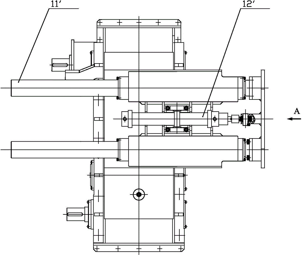
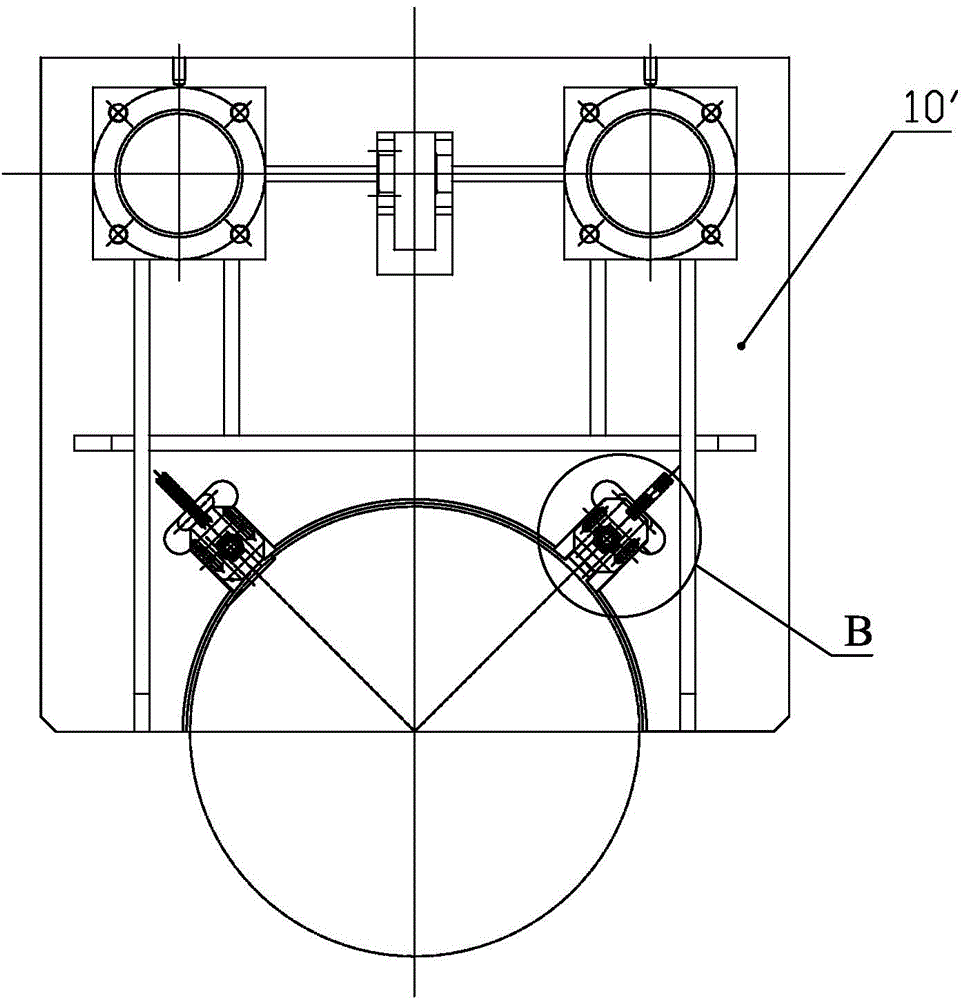
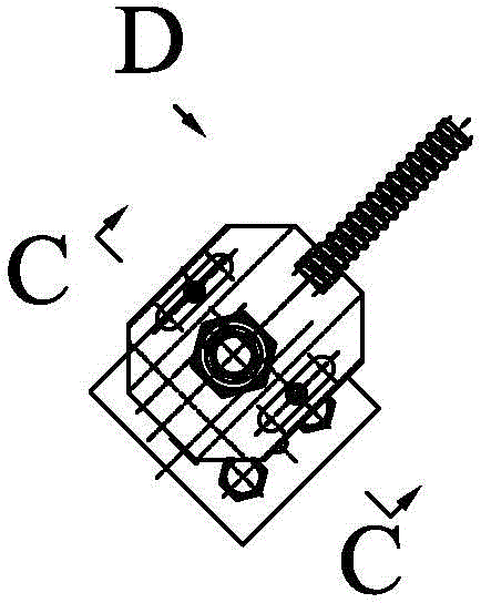
[0038] Such as Figure 6-Figure 12As shown, a side push plate device of a cold-rolled copper strip coiler includes a side push plate frame body 1, a guide rod 2, a hydraulic cylinder 3 and a reel 4, and the side push plate frame body 1 is provided with a pneumatic valve 5. The pneumatic valve 5 includes a cylindrical valve cavity 501 vertically fixed on the rear end of the side push plate frame body 1, a cylindrical valve core 502 located in the valve cavity 501 and fixed on the The control panel 503 at the front end of the spool 502; a sealing ring group 508 is provided between the spool 502 and the valve cavity 501, and the sealing ring group is composed of six sealing rings, and a sealing ring can also be added appropriately according to specific conditions. The number of groups of rings, the side push plate frame body 1 is provided with a through hole 512 for the valve core 502 to pass through, and an elastic support part is also provided between the control board 503 and ...


PUM


Abstract

The invention discloses a side push plate device of a cold rolling copper belt recoiling machine, and relates to the field of cold rolling copper belt recoiling machines. The side push plate device comprises a side push plate frame body, guiding rods, a hydraulic cylinder and a winding drum, wherein a pneumatic valve is arranged on the side push plate frame body; the pneumatic valve comprises a valve cavity fixed on the side push plate frame body, a valve core positioned in the valve cavity and a control plate fixed on the front end of the valve core, and an elastic supporting part is also arranged between the control plate and the cavity wall of the valve cavity; the side push plate frame body is provided with at least two guiding parts, the at least two guiding parts are distributed along the excircle of the winding drum, the guiding rods are arranged on the guiding parts, and the guiding plates are driven by a double-acting air cylinder to radially move along the winding drum. The side push plate device provided by the invention has the advantages that a pneumatic principle is adopted, the lifting movement of the guiding plates is realized through a manner that the pneumatic valve drives an air cylinder piston rod to stretch, and thus a potential safety hazard is eliminated.

Description

technical field [0001] The invention relates to the field of cold-rolled copper strip coilers, in particular to a side push plate device of a cold-rolled copper strip coiler. Background technique [0002] After the copper strip rolling is completed in the cold-rolled copper strip production line, the finished coil after rolling should be unloaded at the position of the entrance (or exit) coiler. The side push plate device of the coiler is used to cooperate with the coil unloading trolley to complete the coil unloading work. [0003] The schematic diagram of the side push plate of the traditional coiler is as follows: Figure 1-Figure 5 shown. The whole side push plate device is installed above the coiling reducer, and is composed of guide rod (11'), pressure cylinder (12'), side push plate frame body (10') and other parts. The guide rod (11') and the hydraulic cylinder (12') are installed on the top of the reducer casing. The side push plate frame (10') is a welded struct...

Claims


Application Information

Patent Timeline
Patent Type & Authority Applications(China)
IPC IPC(8): B21C47/24
Inventor 赵恒亮胡子瑞马江涛
Owner DALIAN HUARUI HEAVY IND GRP CO LTD
Why Eureka
Try Eureka