Laminate bonding device

A technology of bonding and sucking boards, which is applied in the field of laminate devices to achieve the effects of reducing production costs, improving work efficiency and reducing production processes

Inactive Publication Date: 2014-10-08
HUZHOU SUNYARD STAIRS
View PDF5 Cites 4 Cited by
  • Summary
  • Abstract
  • Description
  • Claims
  • Application Information

AI Technical Summary

Problems solved by technology

[0005] In order to overcome the defect of using artificial glue to bond the laminates, the invention provides a laminate bonding device, which will bond the glued wooden boards together. When bonding, there will be no gap between the laminates Mutual movement and tidy bonding, there is no need to use a cutting machine to cut the extra wood, which reduces the production process, reduces the amount of labor used, improves work efficiency, and reduces the production cost of the enterprise

Method used


Image

  • Laminate bonding device
  • Laminate bonding device
  • Laminate bonding device

Examples


Embodiment 1

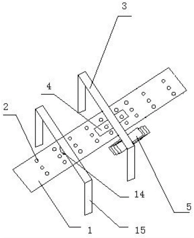
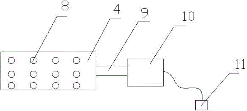
[0032] Such as figure 1 , image 3 , Figure 4 and Figure 5 As shown, in this embodiment, it includes a conveyor belt 1, a pressing mechanism and a laminate box 5. The pressing mechanism includes a crossbeam 3, a vertical beam, a cylinder and a suction plate 4. There are two vertical beams, which are respectively located at the conveying On both sides of the belt 1, the crossbeam 3 is welded on the vertical beam and located above the conveyor belt 1. The crossbeam 3 is provided with a slide rail and a servo motor. Sliding inside, one end of the cylinder is connected to the connecting block, the other end is connected to the suction plate 4, the suction plate 4 is provided with the first negative pressure hole 2, the suction plate 4 is a hollow structure, and the suction plate 4 is connected to the first negative pressure tube 9 , the first negative pressure tube 9 is connected with a first vacuum pump 10, the conveyor belt 1 is provided with a second negative pressure hole...

Embodiment 2

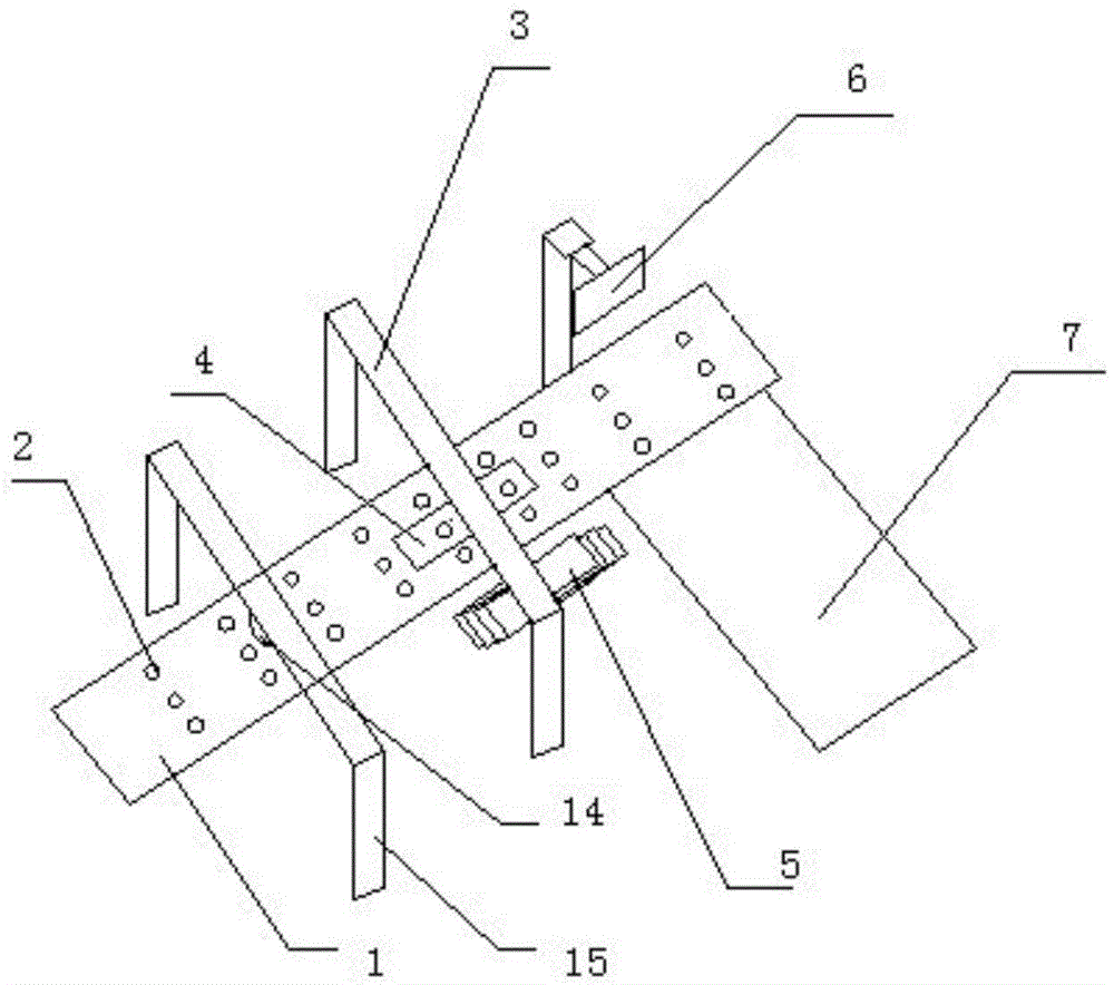
[0038] Such as figure 2 , image 3 , Figure 4 and Figure 5 As shown, it includes a conveyor belt 1, a pressing mechanism and a laminate box 5. The pressing mechanism includes a beam 3, a vertical beam, a cylinder and a suction plate 4. There are two vertical beams, which are respectively located on both sides of the conveyor belt 1. The beam 3 is welded on the vertical beam and is located above the conveyor belt 1. The beam 3 is provided with a slide rail and a servo motor. A connecting block is clamped inside the slide rail. The servo motor drives the connecting block to slide in the slide rail, and one end of the cylinder is connected. On the connection block, the other end is connected with the suction plate 4, the first negative pressure hole 2 is arranged on the suction plate 4, the suction plate 4 is a hollow structure, the suction plate 4 is connected with the first negative pressure tube 9, the first negative pressure tube 9 is connected with a first vacuum pump ...


PUM


Abstract

The invention relates to a laminate bonding device. The laminate bonding device comprises a conveying belt, a press-fit mechanism and a laminate box, wherein the press-fit mechanism comprises a cross beam, two vertical beams, an air cylinder and a suction plate, the two vertical beams are located on two sides of the conveying belt respectively, the cross beam is welded on the vertical beams and located above the conveying belt, a sliding rail and a servo motor are arranged on the cross beam, a connecting block is connected in the sliding rail in a clamped manner, the servo motor drives the connecting block to slide in the sliding rail, one end of the air cylinder is connected onto the connecting block, the other end of the air cylinder is connected with the suction plate, and negative-pressure holes are formed in the suction plate adopting a hollow structure; negative-pressure holes are formed in the conveying belt adopting a hollow structure; meanwhile, the laminate bonding device further comprises a glue brush-coating mechanism. According to the laminate bonding device, the glue brush-coating mechanism substitutes for manual glue brush-coating, so that the working efficiency is improved; during press-fit, laminates do not play and are bonded tidily, so that a cutting machine is not required to cut redundant wood, production procedures are reduced, the manual usage amount is reduced, the working efficiency is improved, and the production cost of an enterprise is reduced.

Description

technical field [0001] The present invention relates to equipment used in furniture production, in particular to a device for bonding laminates for furniture. Background technique [0002] When producing all kinds of wooden furniture, laminates are the most basic material. Since the thickness of laminates has a uniform specification, manufacturers of various production costs will manufacture according to this uniform specification. However, the thickness of the plywood required for the production of different wooden furniture is not the same. In order to obtain the required thickness of the laminate, it is necessary to press and bond the laminates together, and the current method is that the worker brushes a layer of glue on the laminate, and then presses another laminate on it to bond together Finally, use machine pressing to complete the bonding work of the laminates. The advantage of this method is that it is simple to operate, but it has many defects: [0003] 1. The ...

Claims


Application Information

Patent Timeline
Patent Type & Authority Applications(China)
IPC IPC(8): B27G11/00B27D3/00
Inventor 张金财
Owner HUZHOU SUNYARD STAIRS
Why Eureka
Try Eureka