Blast furnace smoke recycling device

A flue gas recovery and blast furnace technology, applied in blast furnaces, blast furnace details, furnaces, etc., can solve the problems of increasing project investment, large layout space, etc., and achieve the effect of reducing project investment and floor space, and achieving good dehydration and water sealing effects.

Inactive Publication Date: 2014-10-08
PANGANG GRP ENG TECH
View PDF5 Cites 5 Cited by
  • Summary
  • Abstract
  • Description
  • Claims
  • Application Information

AI Technical Summary

Problems solved by technology

The spray tower, dehydrator and water seal used in the above cooling methods are all separately arranged structures, which increases engineering investment and requires a large layout space

Method used


Image

  • Blast furnace smoke recycling device
  • Blast furnace smoke recycling device
  • Blast furnace smoke recycling device

Examples


Embodiment Construction

[0015] In the following, the blast furnace flue gas recovery and utilization device of the present invention will be described in detail in conjunction with exemplary embodiments.

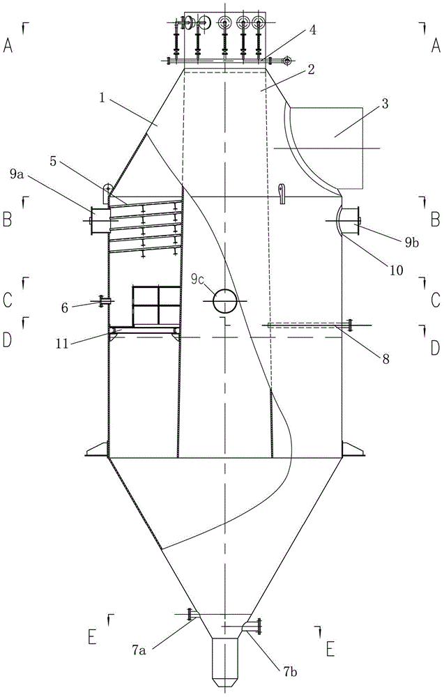
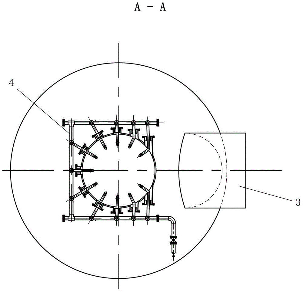
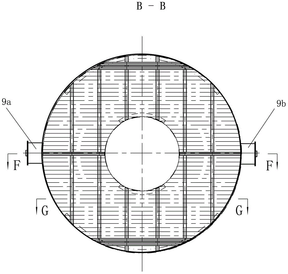
[0016] The blast furnace flue gas recovery and utilization device according to the present invention includes: a tower body, a horn tube, an air outlet pipe, a spray component, a dehydration component and a water injection pipe, wherein the tower body is surrounded by the tower wall and has a closed cavity; the horn tube is arranged In the inner cavity of the tower, the small end of the horn tube protrudes from the top of the tower body, a predetermined space is left between the large end of the horn tube and the bottom of the tower body, and the spray member is arranged above the horn tube to direct the small end from the horn tube. The blast furnace flue gas entering at the end is sprayed with cooling water; the dehydration component is arranged between the outer surface of the horn tube and the inne...


PUM


Abstract

The invention provides a blast furnace smoke recycling device. The blast furnace smoke recycling device comprises a tower body, a horn-shaped pipe, a smoke outlet pipe, a spraying component, a dehydrating component and a water injection pipe, wherein the horn-shaped pipe is arranged in the inner cavity of the tower body, the small end of the horn-shaped pipe extends from the top of the tower body, a predetermined space is kept between the big end of the horn-shaped pipe and the bottom of the tower body, and the spraying component is arranged above the horn-shaped pipe; the dehydrating component is arranged between the outer surface of the horn-shaped pipe and the inner surface of the wall of a tower; the smoke outlet pipe is arranged on the tower body and is communicated with the part, arranged above the dehydrating component, of the inner cavity of the tower body; the water injection pipe is arranged on the tower body and is communicated with a part, arranged below the dehydrating component, of the inner cavity of the tower body, and the water injection pipe is arranged on the big end of the horn-shaped pipe. The blast furnace smoke recycling device realizes smoke cooling, dehydrating and water sealing functions at the same time, project investment and occupying area are reduced, and the blast furnace smoke recycling device has the advantage of good cooling, dehydrating and water sealing effects.

Description

Technical field [0001] The invention relates to a blast furnace clean gas treatment equipment, and more specifically, to a device for recycling and utilizing blast furnace flue gas after dust removal and purification. Background technique [0002] The blast furnace gas is called clean gas after purification and dust removal. Because the temperature of the purified gas is relatively high, it needs to be cooled before entering the main gas pipe network. When the natural cooling method is used for cooling, there are problems such as long time and long heat dissipation pipes. At present, the most common way to cool the clean gas is water cooling, that is, by setting up a spray tower to spray cooling water mist and exchange heat with the clean gas to reduce the temperature of the clean gas. The clean gas after water cooling contains a lot of moisture. Therefore, a dehydrator is required, and a separate water seal or water seal valve is also required to achieve gas sealing. The spray...

Claims


Application Information

Patent Timeline
Patent Type & Authority Applications(China)
IPC IPC(8): C21B5/06
CPCY02P10/20Y02P10/25
Inventor 吴燕博何平李红军胥中平杨利兵肖晓清
Owner PANGANG GRP ENG TECH
Why Eureka
Try Eureka