Eureka AIR delivers breakthrough ideas for toughest innovation challenges, trusted by R&D personnel around the world.

Gas boiler system

A gas-fired boiler and flue gas technology, applied in the direction of combustion method, combustion type, combustion equipment, etc., can solve the problems of low efficiency, difficulty in popularization and use, increased investment and operating costs, etc., and achieve the effect of cost saving and emission reduction

Inactive Publication Date: 2014-10-08
北京华通兴远供热节能技术有限公司 +1
View PDF6 Cites 6 Cited by
  • Summary
  • Abstract
  • Description
  • Claims
  • Application Information

AI Technical Summary

Problems solved by technology

[0004] However, the denitrification treatment in some small and medium-sized gas-fired boilers is still a blank. This is because the content of nitrogen oxides in the flue gas produced in small and medium-sized natural gas boilers is relatively low. The denitrification treatment of the equipment will greatly increase the investment and operating costs, which will result in the high cost of gas boiler denitrification but the low benefit, making it difficult to popularize and use

Method used


Image

  • Gas boiler system
  • Gas boiler system

Examples


Embodiment Construction

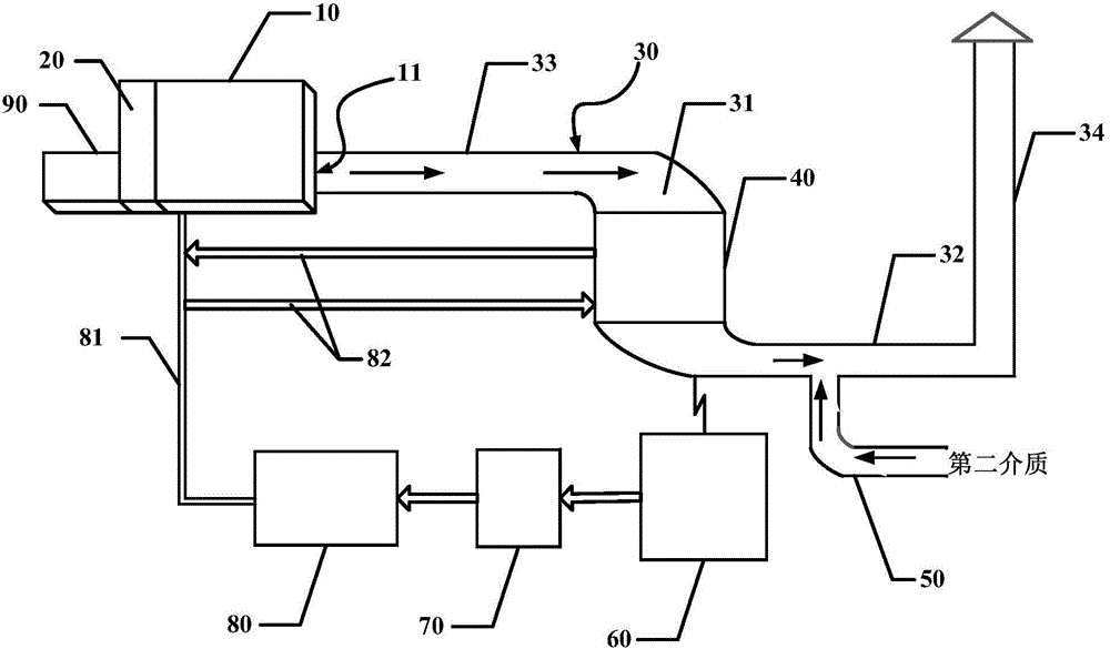
[0022] figure 1 It is a schematic structural diagram of a gas boiler system according to an embodiment of the present invention. Such as figure 1 As shown, the gas boiler system of the embodiment of the present invention may generally include a furnace body 10, a catalytic reactor 20, a flue gas discharge pipeline 30, a flue gas waste heat utilization device 40 arranged in the flue gas discharge pipeline, and The flue gas recooling device 50 in the flue gas discharge pipeline and located downstream of the flue gas waste heat utilization device 40.

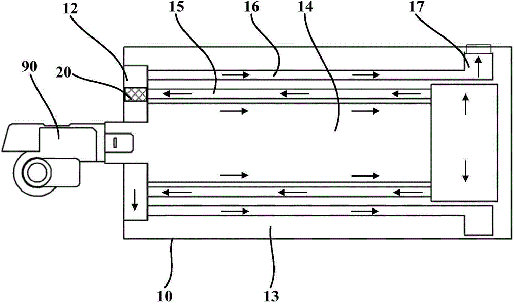
[0023] The furnace body 10 has a flue gas discharge port 11 for discharging combustion flue gas. The catalytic reactor 20 is arranged in the furnace body 10 to promote the NO in the flue gas to be oxidized to NO before being discharged from the flue gas outlet 11 2 . The flue gas discharge pipe 30 is arranged outside the furnace body 10 and connected to the flue gas outlet 11 of the furnace body 10 for receiving the flue gas discharg...


PUM


Abstract

The invention discloses a gas boiler system, which comprises a furnace body, a catalytic reactor, a smoke exhaust pipeline, a smoke residual heat utilizing device and a smoke re-cooling device, wherein a smoke exhaust opening is formed in the furnace body; the catalytic reactor is arranged in the furnace body and is used for promoting NO in the smoke to be oxidized to NO2 before the smoke is exhausted from the smoke exhaust opening; the smoke exhaust pipeline is arranged outside the furnace body, is connected with the smoke exhaust opening of the furnace body and is used for receiving exhausted smoke and exhausting the smoke to the atmosphere; the smoke residual heat utilizing device is arranged in the smoke exhaust pipeline and is used for receiving the smoke exhausted from the furnace body, so that the smoke exchanges heat with a first medium to heat the first medium and cool the smoke to separate out condensate water; the smoke re-cooling device is arranged at the downstream of the smoke residual heat utilizing device and is used for further cooling the smoke exhausted from the smoke residual heat utilizing device; while working, the condensate water is used for absorbing NO2 in the smoke. According to the gas boiler system, at the time that the emission of nitrogen oxide is greatly reduced, deep recycling of residual heat of smoke condensing is realized.

Description

Technical field [0001] The invention relates to the technical field of energy saving and emission reduction of natural gas boilers, in particular to a gas boiler system. Background technique [0002] At present, China is paying more and more attention to energy conservation and emission reduction in various fields of society. Although the emission standards of nitrogen oxides have been increasingly emphasized in recent years, the denitrification treatment of flue gas from large-scale coal-fired boilers in the industrial field has become more common, and the corresponding technologies are also relatively more. Mature, although the nitrogen oxide content discharged into the atmosphere also meets China’s latest emission standards, the denitration treatment of flue gas from large-scale coal-fired boilers in these industrial fields generally adopts the method of reducing NO, and is mainly for large-scale coal-burning The flue gas with high nitrogen oxide content produced by the boiler...

Claims


Application Information

Patent Timeline
IPC IPC(8): F23C13/00F23J15/04F23J15/06
CPCY02E20/30
Inventor 杨勇禚玉群赵一波王随林
Owner 北京华通兴远供热节能技术有限公司
Why Eureka
Eureka Blog
Learn More