Petroleum catalytic cracking processing method
A catalytic cracking and petroleum technology, which is applied in the field of petroleum refining, can solve the problems of low yield of target products and unsatisfactory product distribution, and achieve the effect of increasing yield, improving distribution of cracked products, and reducing investment in transformation
- Summary
- Abstract
- Description
- Claims
- Application Information
AI Technical Summary
Problems solved by technology
Method used
Image


Examples
Embodiment 1
[0028] As shown in the figure, the process flow of the method for processing petroleum fractions provided by the present invention is described as follows:
[0029] (1) The raw oil from the raw oil storage tank 1 is heated by the heating furnace 2, then mixed with the atomized water 3, and enters the catalytic cracking reactor 6 to undergo a catalytic cracking reaction, and the generated oil and gas product 7 is in contact with the carbon deposit. The active catalyst spent agent 8 is separated at the top of the reactor 6, the oil and gas product 7 is sent to the distillation tower 17 through the pipeline, and the catalyst spent agent 8 deactivated by carbon deposits is sent to the stripping tower 10.
[0030] (2) The stripping medium 9 is sent into the stripping tower 10 through the pipeline, and the catalyst standby agent 8 is stripped to remove the oil and gas products adsorbed by the catalyst, and the oil and gas products are mixed with the oil and gas products 7 coming out ...
Embodiment 2
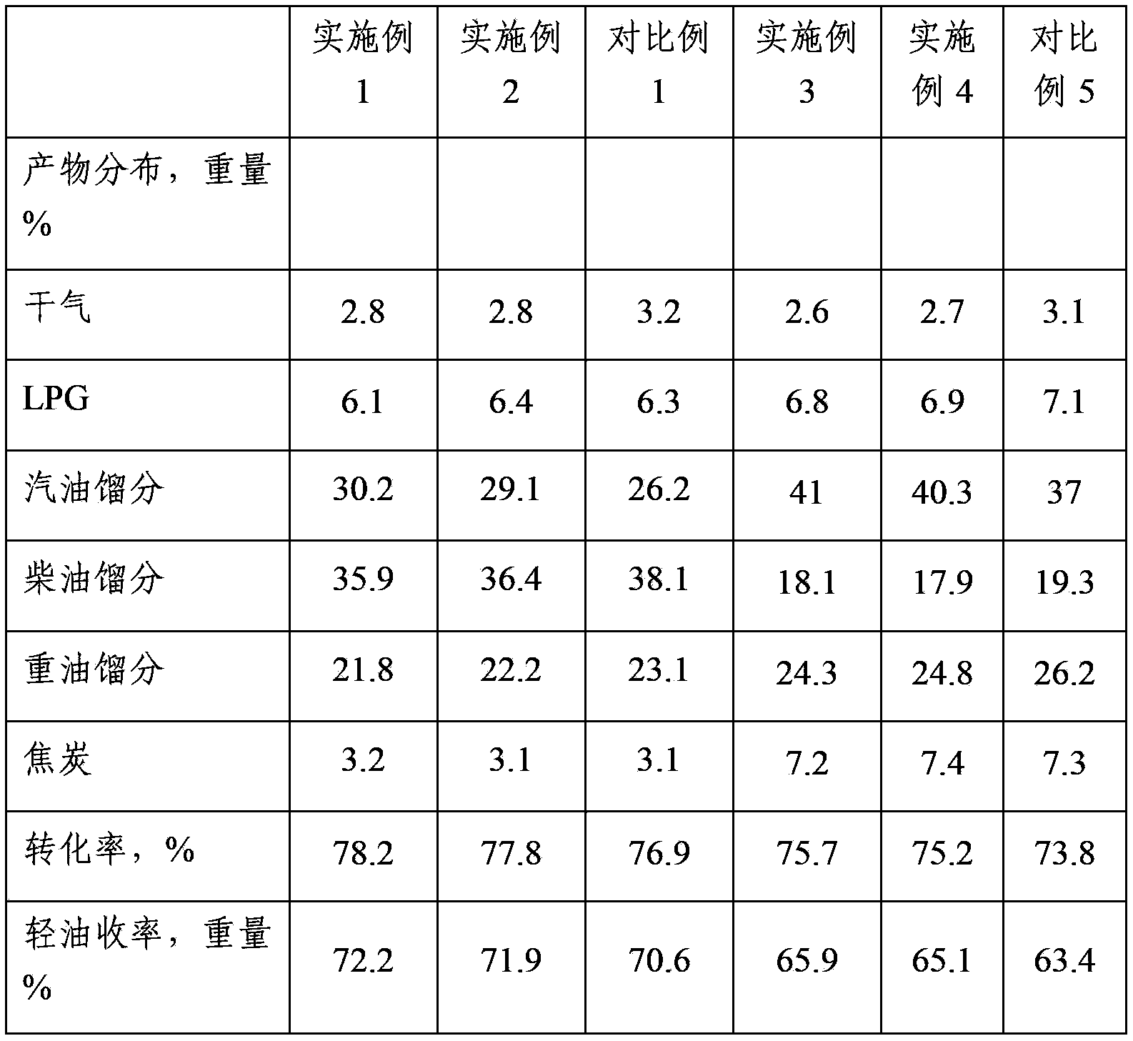
[0034]Using oil A (see Table 1 for its properties) as feedstock oil, in a small riser reactor with catalyst inlets on the side wall and bottom, it contacts with the catalytic cracking catalyst of commercial brand DVR-3 to undergo catalytic cracking reaction. The bottom inlet enters the reactor, the side wall inlet is at the lower 1 / 5 of the reactor, and the catalyst flow ratio between the bottom inlet and the side wall inlet is 5:5. The catalytic cracking process conditions are: the reactor outlet temperature is 502°C, the catalyst-to-oil ratio is 4.5, and the regeneration temperature is 666°C. The distribution of catalytic cracking products is shown in Table 2.
Embodiment 3
[0039] Using oil B (see Table 1 for its properties) as feedstock oil, in a small riser reactor with catalyst inlets on the side wall and bottom, contact with the catalytic cracking catalyst of commercial brand RMG-2 for catalytic cracking reaction, feedstock oil from The bottom inlet enters the reactor, the side wall inlet is at the lower 1 / 4 position of the reactor, and the catalyst flow ratio between the bottom inlet and the side wall inlet is 6:4. The catalytic cracking process conditions are: the reactor outlet temperature is 498 ° C, the catalyst oil ratio is 4.5, the regeneration temperature is 683 ° C, and the distribution of catalytic cracking products is shown in Table 2.
PUM
 Abstract
Description
Claims
Application Information