Injection pressurized casing gas recovery device

A technology for recovering device and casing gas, which is applied in the fields of production fluids, wellbore/well components, and earth-moving drilling, etc. It can solve the problems of reducing the effective production pressure drop of oil wells, affecting pump efficiency, and unstable air pressure, and avoiding environmental pollution. and waste, improve device utilization, and facilitate installation and transportation.

Active Publication Date: 2018-08-03
CHINA UNIV OF PETROLEUM (EAST CHINA)
View PDF3 Cites 1 Cited by
  • Summary
  • Abstract
  • Description
  • Claims
  • Application Information

AI Technical Summary

Problems solved by technology

[0002] In oilfield crude oil extraction, as the pressure of reservoir fluid decreases, light components in crude oil, such as methane, ethane, propane, etc., will volatilize from the annular space between casing and tubing to form casing gas. A gas column with a certain pressure is formed, which forces the dynamic liquid level of the oil well to drop, so that the effective production pressure drop of the oil well is reduced, and the production capacity is reduced; a part of the gas enters the pump cavity with the liquid flow, occupies a certain space in the pump cavity, and affects the pump efficiency. "Air lock" occurs, making the well pump unable to work
[0003] Due to the low output of oil well casing gas and the unstable pressure, there is no special gas pipeline to transport casing gas, and the casing gas cannot be recovered and utilized effectively. Strip burning or directly exhaust the casing gas
[0004] In order to solve this problem, there are currently three methods for recovering casing gas: one is to use the power of the pumping unit itself to drive the plunger to recover the casing gas, and pressurize it to enter the wellhead pipeline; this device has a complex structure, and Only suitable for pumping unit oil production, not for submersible pump oil production
The other is to use an air compressor device to increase the pressure of the casing gas, separate the gas from the liquid, and treat the harmful gas before entering the gas storage tank; this method has large investment, high maintenance and management costs, and large power consumption, which is economical. The benefit is not obvious, so it has not been promoted and applied

Method used


Image

  • Injection pressurized casing gas recovery device

Examples


Embodiment Construction

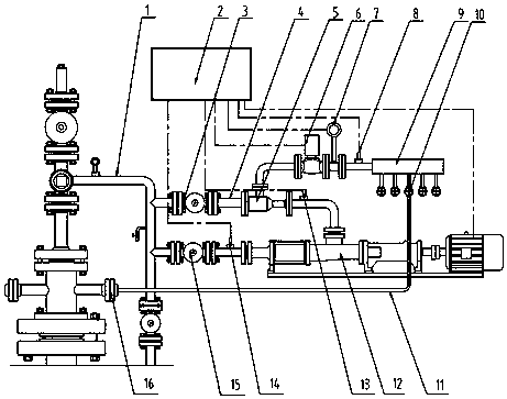
[0013] The structure and implementation of the present invention will be described in detail below in conjunction with the accompanying drawings.

[0014] The whole device includes injector 5, gas-liquid mixing pump 12, liquid inlet valve 3, liquid outlet valve 15, electric valve 6, air intake valve 10, gas storage tank 9, gas pressure sensor 8, gas flow meter 7, electric The valve 6, the control unit 2, etc. are integrally made into a skid-mounted block. The liquid inlet of the ejector 5 is connected to the upstream of the oil well outlet pipeline 1 through the oil delivery hose 4 and the liquid inlet valve 3, and the liquid outlet is connected to the inlet of the gas-liquid mixed transport pump 12; An intermediate pressure sensor 13 is designed to facilitate the observation of the working state of the injector 5; the outlet of the gas-liquid mixed pump 12 is connected to the downstream of the oil well outlet pipeline 1 through the oil delivery hose 4 and the outlet valve 15,...


PUM


Abstract

The invention provides an injection pressurized casing gas recovery device, which is used for recovering the casing gas in the wellhead of an oil field. The device includes: ejector, gas-liquid mixed pump, liquid inlet valve, liquid outlet valve, inlet valve, gas storage tank, gas pressure sensor, gas flow meter, electric valve, control unit, etc., and is made into a skid-mounted piece. The liquid inlet of the ejector is connected with the upstream of the oil well oil outlet pipeline, and the liquid outlet is connected with the inlet of the gas-liquid mixed transport pump. When working normally, both the liquid inlet valve and the liquid outlet valve are opened. When the pressure of the casing gas reaches a certain value, the gas pressure sensor sends a signal to the control unit, and the control unit sends an instruction to start the mixed pump and open the electric valve after a delay; The high-speed flowing liquid in the introducer attracts the casing gas, and after mixing, it enters the mixed transport pump for pressurization, and then enters the oil well outlet pipeline to realize the recovery of the casing gas and avoid the damage caused by burning or venting the casing gas. Energy waste and air pollution.

Description

technical field [0001] The invention relates to an injection pressurized casing gas recovery device, which is used for recovering the casing gas produced in the process of oil recovery in an oil field. Background technique [0002] In oilfield crude oil extraction, as the pressure of reservoir fluid decreases, light components in crude oil, such as methane, ethane, propane, etc., will volatilize from the annular space between casing and tubing to form casing gas. A gas column with a certain pressure is formed, which forces the dynamic liquid level of the oil well to drop, so that the effective production pressure drop of the oil well is reduced, and the production capacity is reduced; a part of the gas enters the pump cavity with the liquid flow, occupies a certain space in the pump cavity, and affects the pump efficiency. An "air lock" occurs, making the well pump inoperable. [0003] Due to the low output of oil well casing gas and the unstable pressure, there is no speci...

Claims


Application Information

Patent Timeline
Patent Type & Authority Patents(China)
IPC IPC(8): E21B43/00
Inventor 赵军友王秀会王少波孙乾刘祥猛万法伟孙晓山张蕊蕊
Owner CHINA UNIV OF PETROLEUM (EAST CHINA)
Why Eureka
Try Eureka