
Floating gate structure and manufacturing method thereof

A manufacturing method and floating gate technology, applied in electrical components, circuits, semiconductor devices, etc., can solve problems such as sharp corners of floating gate polysilicon, offset of floating gate polysilicon, thin thickness of floating gate polysilicon, etc., to save mask costs Effect

Inactive Publication Date: 2014-10-15
WUHAN XINXIN SEMICON MFG CO LTD
View PDF5 Cites 9 Cited by
  • Summary
  • Abstract
  • Description
  • Claims
  • Application Information

AI Technical Summary

Problems solved by technology

For example: for the conventional method, (1) two photolithography of the active area and the floating gate are used, which increases the cost of the mask and process
(2) The alignment of the polysilicon floating gate to the active area is a process challenge, and it is prone to offset of the floating gate polysilicon to the active area
Therefore not suitable for 65nm and more advanced processes
(3) The corners of the floating gate polysilicon are sharp, which is not conducive to the subsequent deposition of the floating gate-control gate isolation layer, and the sharp corners are easy to form a channel for the escape of stored charges
[0007] For the floating gate-active region self-alignment process, there are the following defects: (1) Because the etch back amount of the shallow trench isolation oxide layer is determined by the subsequent polysilicon deposition, it is not conducive to controlling the coupling amount of the control gate polysilicon to the floating gate polysilicon
(2) Process challenges of polysilicon deposition, prone to polysilicon deposition voids
(3) Due to the process limitations of polysilicon deposition and polysilicon planarization, the thickness of floating gate polysilicon is thin, which is not conducive to the preservation of stored charges

Method used


Image

  • Floating gate structure and manufacturing method thereof
  • Floating gate structure and manufacturing method thereof
  • Floating gate structure and manufacturing method thereof

Examples


Embodiment Construction

[0044] The manufacturing method of the floating gate structure of the present invention will be described in more detail below in conjunction with schematic diagrams, wherein a preferred embodiment of the present invention is shown, and it should be understood that those skilled in the art can modify the present invention described here and still realize the present invention beneficial effect. Therefore, the following description should be understood as the broad knowledge of those skilled in the art, but not as a limitation of the present invention.

[0045] In the interest of clarity, not all features of an actual implementation are described. In the following description, well-known functions and constructions are not described in detail since they would obscure the invention with unnecessary detail. It should be appreciated that in the development of any actual embodiment, numerous implementation details must be worked out to achieve the developer's specific goals, such ...


PUM


Abstract

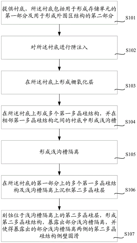
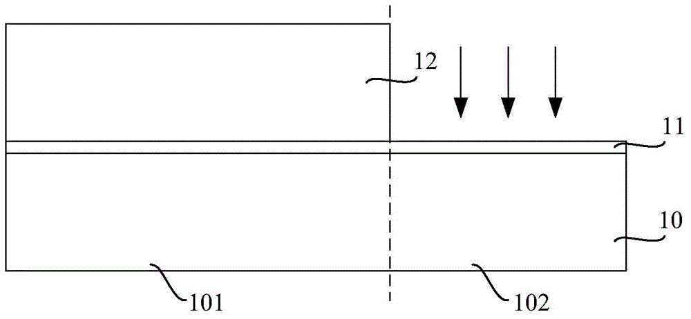
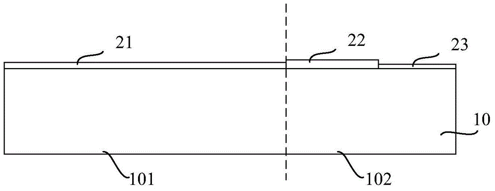
The invention discloses a floating gate structure and a manufacturing method thereof. The method comprises the steps of providing a substrate which comprises a first part and a second part, performing well injection on the substrate, continuously forming a gate oxide layer, then forming a plurality of first polycrystalline silicon structures, forming shallow grooves in the substrate between the adjacent first polycrystalline silicon structures, forming shallow groove isolation, depositing a second polycrystalline silicon layer on the first polycrystalline silicon structures and the shallow groove isolation on the first part, etching the second polycrystalline silicon layer, forming second polycrystalline silicon structures, exposing partial shallow groove isolation, and allowing side walls of the second polycrystalline silicon structures on the two sides of the exposed partial shallow groove isolation to be smooth. The method saves a photomask, simplifies a technology, and achieves perfect alignment of floating gate polycrystalline silicon and an active region. An application of a floating gate polycrystalline silicon side wall technique meets a control gate and floating gate coupling requirement, eliminates a sharp corner, and facilitates storing charge in floating gate polycrystalline silicon.

Description

technical field [0001] The invention relates to the technical field of semiconductors, in particular to a floating gate structure and a manufacturing method thereof. Background technique [0002] With the rapid development of portable electronic devices, the requirements for data storage are getting higher and higher. Semiconductor memory for storing data is classified into volatile memory and nonvolatile memory. Among non-volatile memories, flash memory (flash memory) has become an extremely important device due to its high chip storage density and better process adaptability. The flash memory with floating gate structure is a hot topic in flash memory. [0003] In floating gate flash memory products, there are two main types of polysilicon floating gate technology: [0004] 1. Conventional processes, including: ① active area photolithography, etching, ② shallow trench isolation oxide layer deposition, etch back, ③ floating gate polysilicon deposition, ④ floating gate po...

Claims


Application Information

Patent Timeline
Patent Type & Authority Applications(China)
IPC IPC(8): H01L29/423H01L21/28
CPCH01L29/66825H01L29/42324
Inventor 于绍欣
Owner WUHAN XINXIN SEMICON MFG CO LTD
Learn More