Sand cooling apparatus
A technology of sand cooling and diversion device, which is applied to casting molding equipment, machinery for cleaning/processing of casting materials, metal processing equipment, etc. and other problems, to achieve the effect of simple structure, reduced energy consumption, convenient and quick transformation
- Summary
- Abstract
- Description
- Claims
- Application Information
AI Technical Summary
Problems solved by technology
Method used
Image

Examples
Embodiment 1)
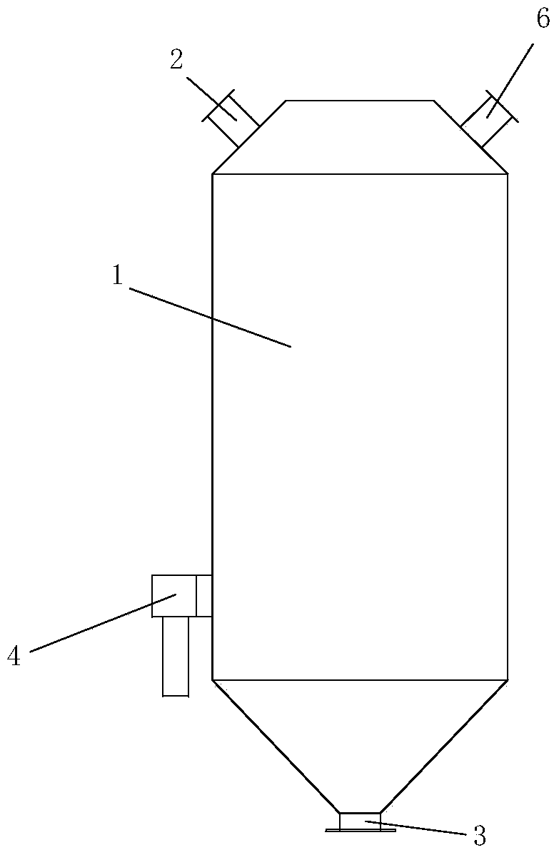
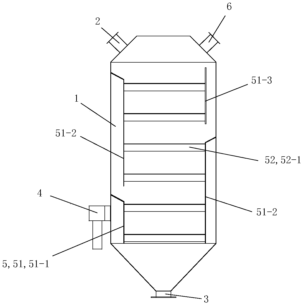
[0049] See figure 1 , figure 2 and Figure 5 , The sand cooling device of this embodiment includes a vertical box 1, a feed port 2, a discharge port 3, an air inlet 4, a flow guiding device 5 and an air outlet 6.
[0050] See figure 1 , figure 2 and Figure 5 , the feed inlet 2 is airtightly and fixedly connected to the upper left side of the vertical box body 1 from the upper left, and communicates with the inside of the vertical box body 1 . The feed port 2 is provided with a corresponding valve which can control the feed port 2 to be in an open state or a closed state. The discharge port 3 is airtightly and fixedly connected to the lower end of the vertical box body 1 from below, and communicates with the inside of the vertical box body 1 . The discharge port 3 is provided with a corresponding valve, and the molding sand in the vertical box body 1 can be released by opening the valve. The lower part of the box body plate of the vertical box body 1 is provided with ...
Embodiment 2)
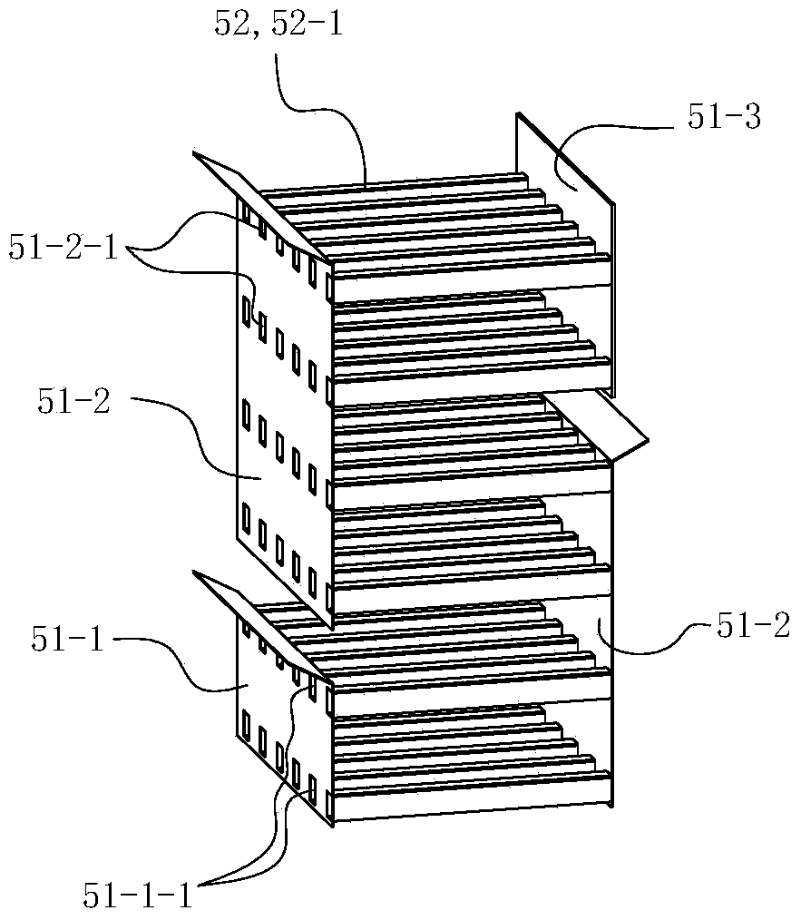
[0062] See Figure 7 , the rest of this embodiment is the same as Embodiment 1, the difference is: the lower air outlet 51-1-1 of the air inlet plate 51-1 of the flow guiding device 5, the communication air port 51-2-2 of the communication plate 51-2 1 and the upper air outlet 51-3-1 of the air outlet plate 51-3 are all provided with installation grooves 53 on the side close to the axis of the vertical box body, and the cross-sectional shape of each installation groove 53 is consistent with the bottom of the air inlet plate 51-1. The cross-sectional shape of the air outlet 51-1-1 is corresponding. Each installation groove 53 is airtightly and fixedly connected with the contacting part of the corresponding air inlet plate 51-1, communication plate 51-2 or air outlet plate 51-3, and the opening is downward. Each guide groove 52 - 1 is fixedly arranged on the corresponding two installation grooves 53 overlapping from top to bottom.
Embodiment 3)
[0064] See Figure 8 , the rest of this embodiment is the same as that of Embodiment 1, and the difference is that the cross-sectional shape of each flow guide groove 52-1 of the air outlet flow guide groove group 52 of the flow guide device 5 is the same as that of the air inlet plate 51-1. The rectangular cross-section of the gas port 51-1-1 corresponds to a rectangular shape. Each diversion groove 52-1 of the air outlet diversion groove group 52 of the diversion device 5 is provided with two protective plates 52-1-1. The two protective plates 52-1-1 are arranged on the diversion The junction of the groove walls on the front and rear sides of the groove 52-1 and the groove bottom on the upper side.
PUM
 Abstract
Description
Claims
Application Information
 - R&D
- Intellectual Property
- Life Sciences
- Materials
- Tech Scout
- Unparalleled Data Quality
- Higher Quality Content
- 60% Fewer Hallucinations
Browse by: Latest US Patents, China's latest patents, Technical Efficacy Thesaurus, Application Domain, Technology Topic, Popular Technical Reports.
© 2025 PatSnap. All rights reserved.Legal|Privacy policy|Modern Slavery Act Transparency Statement|Sitemap|About US| Contact US: help@patsnap.com