Supercharge Your Innovation With Domain-Expert AI Agents!

Serial transmission apparatus and transmission method of electric energy system

A transmission device and transmission method technology, applied in the direction of circuit devices, electrical components, etc., can solve the problems of high maintenance costs and large investment in communication hardware equipment, and achieve the effect of facilitating popularization and utilization and reducing hardware investment costs

Inactive Publication Date: 2014-10-22
JIANGYIN POWER SUPPLY OF JIANGSU ELECTRICPOWER +2
View PDF3 Cites 0 Cited by
  • Summary
  • Abstract
  • Description
  • Claims
  • Application Information

AI Technical Summary

Problems solved by technology

[0002] With the construction of the power transmission pipeline network, the number of substations has increased dramatically. Taking Jiangyin Power Supply Company as an example, there are nearly 150 existing plants and stations, of which there are nearly 50 user substations under the jurisdiction. The data signals of the ammeters of each substation need to be connected In the power-input energy system, there are more than 20 electric meter data signals in conventional bureau-owned substations, which are transmitted using dedicated data servers and dispatching data network equipment. Since user transformers and power plants are not equipped with dispatching data network equipment, the amount of electricity data collected is generally one to two. If the standard transmission channel is used, dispatching data network equipment and optical fiber transmission channel shall be installed in the user substation and the power plant, or GPRS mobile data public network wireless transmission shall be adopted. It is necessary to install special secondary security equipment for the power system to ensure data security. The communication hardware equipment of the two requires a large investment and high maintenance costs

Method used


Image

  • Serial transmission apparatus and transmission method of electric energy system
  • Serial transmission apparatus and transmission method of electric energy system

Examples


Embodiment Construction

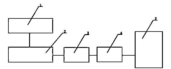
[0016] see Figure 1-2 , the present invention relates to a serial port transmission device for electric energy systems, the device includes a substation meter 1 installed in a substation, the 458 signal output port of the substation meter 1 is connected to a 485 / 232 serial port conversion device 2, the The 232 signal output port of the 485 / 232 serial port conversion device 2 is connected to the MOXA communication server 4 through the communication serial port channel 3, and the output port of the MOXA communication server 4 is connected to the electric energy system server 5 through the network;

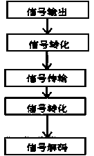
[0017] A serial port transmission method of an electric energy system, said method comprising the following steps:

[0018] Step 1. Obtain the 485 signal of the electric meter in the substation:

[0019] Step 2. Convert the obtained 485 signal into a 232 serial port signal;

[0020] Step 3, converting the obtained 232 serial port signal into a network message;

[0021] Step 4: Th...


PUM


Abstract

The invention relate to a serial transmission apparatus and transmission method of an electric energy system. The apparatus comprises a transformer substation ammeter (1) installed in a transformer substation; a 458 signal output port of the transformer substation ammeter (1) is connected with a 485 / 232 serial conversion device (2); a 232 signal output port of the 485 / 232 serial conversion device (2) is connected to an MOXA communication server (4) by a communication serial channel (3); and an output port of the MOXA communication server (4) is communicated to an electric energy system server (5) by a network. The method comprises the following steps: step one, obtaining a 485 signal of the ammeter in the transformer substation; step two, converting the obtained 485 signal into a 232 serial signal; step three, converting the obtained 232 serial signal into a network message; and step four, sending the network message obtained by conversion in the step three to a remote server by a network to carry out receiving and decoding. According to the invention, with the apparatus and the method, the hardware investment is low.

Description

technical field [0001] The invention relates to a transmission device, that is, a transmission method, in particular to an electric energy system serial port transmission device and a transmission method applied to a power system, and belongs to the technical field of power equipment. Background technique [0002] With the construction of the power transmission pipeline network, the number of substations has increased dramatically. Taking Jiangyin Power Supply Company as an example, there are nearly 150 existing plants and stations, of which there are nearly 50 user substations under the jurisdiction. The data signals of the ammeters of each substation need to be connected In the power-input energy system, there are more than 20 electric meter data signals in conventional bureau-owned substations, which are transmitted using dedicated data servers and dispatching data network equipment. Since user transformers and power plants are not equipped with dispatching data network eq...

Claims


Application Information

Patent Timeline
IPC IPC(8): H02J13/00
Inventor 卢红巫国荣陈琳钱宇赵丽艳
Owner JIANGYIN POWER SUPPLY OF JIANGSU ELECTRICPOWER
Features
  • R&D
  • Intellectual Property
  • Life Sciences
  • Materials
  • Tech Scout
  • Unparalleled Data Quality
  • Higher Quality Content
  • 60% Fewer Hallucinations
Learn More