Rebar groove welding method

A technology of groove welding and steel bars, applied in welding equipment, arc welding equipment, manufacturing tools, etc., can solve problems such as low production efficiency, affecting welding quality, and unstable welding quality, so as to improve production efficiency, increase welding speed and Work efficiency and manpower reduction effect

Inactive Publication Date: 2014-10-29
STATE GRID CORP OF CHINA +1
View PDF7 Cites 7 Cited by
  • Summary
  • Abstract
  • Description
  • Claims
  • Application Information

AI Technical Summary

Problems solved by technology

Welding of steel bar by using electrode arc welding welding method, due to the characteristics of this welding method, it has the disadvantages of low production efficiency and unstable welding quality
And solid wire CO 2 Gas metal arc welding itself is a low-hydrogen welding method. Before welding, the steel surface is required to be clean and free of dirt. However, there are rust and other dirt on the surface of the actual steel bar welding, so defects such as pores and slag inclusions inevitably exist after the steel bar is welded. , affecting welding quality

Method used


Image

  • Rebar groove welding method
  • Rebar groove welding method
  • Rebar groove welding method

Examples


Embodiment approach

[0038] First, prepare the machine tools and welding materials:

[0039] ① Welding equipment chooses NB-350 inverter CO with good characteristics 2 Gas shielded welding machine;

[0040] ② The welding wire is ER501T-1 diameter 1.2mm flux core CO 2 Gas shielded welding wire.

[0041] Secondly, the pairing of welding test pieces is carried out:

[0042] ① Two Φ25mm HRB335 reinforced steel bars and two Q235 steel backing plates with a thickness of 5mm and 100×100mm are selected for the welding test piece;

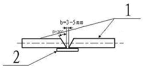
[0043] ② if figure 1 The schematic diagram of the pairing positions of the grooves of the two sections of steel bars is shown, and the two steel bars 1 and one steel plate 2 are arranged according to figure 1 way levels are grouped together;

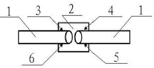
[0044] ③ Choose ER501T-1 diameter 1.2mm core CO 2 Gas shielded welding wire, according to figure 2 4 sections of 10-20mm long tack welding are performed at the positions shown.

Embodiment 1

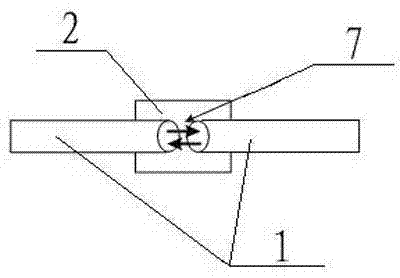
[0046] ① Main welding bead of steel bar: Use 280A welding current I and 24.2V arc voltage U, and the arc moves along the welding seam in a reciprocating straight line, such as image 3 As shown, the arc trajectory on the main welding bead of the steel bar is shown by the arrow marked 7, the welding speed is 36-40cm / min, and the welding time of the first layer is 0.5min;

[0047] ② Backing plate strengthening weld bead: Use 270A welding current I with 23.8V arc voltage U, and the arc moves in a straight line along the weld seam, such as Figure 4 As shown, the arc trajectory on the backing plate strengthening welding bead is shown by the arrow of label 8, the welding speed is 25-35cm / min, and the welding time of the first layer is 0.5min;

[0048] ③ Due to the large welding current I and arc voltage U, a small amount of slag that exists after the first layer of welding is completed at a faster speed will be fully melted and floated out by the relatively slower speed of the cove...

Embodiment 2

[0050] ① Main welding bead of steel bar: use 290A welding current I with 24.6V arc voltage U, and the arc moves along the weld seam in a reciprocating straight line, such as image 3 As shown, the arc trajectory on the main welding bead of the steel bar is shown by the arrow marked 7, the welding speed is 36-50cm / min, and the welding time of the first layer is 0.6min;

[0051] ② Backing plate strengthening weld bead: Use 280A welding current I with 24.2V arc voltage U, and the arc moves in a straight line along the weld seam, such as Figure 4 As shown, the arc trajectory on the backing plate strengthening welding bead is shown by the arrow of label 8, the welding speed is 20-35cm / min, and the welding time of the first layer is 0.6min;

[0052] ③ Due to the large welding current I and arc voltage U, a small amount of slag that exists after the first layer of welding is completed at a faster speed will be fully melted and floated out by the relatively slower speed of the cover ...


PUM


Abstract

The invention discloses a rebar groove welding method. The rebar groove welding method includes the following steps that first, preparation is made before welding, wherein two rebars needing to be welded are paired, and grooves of the rebars are correspondingly arranged horizontally; second, positioned welding is performed, wherein gas metal arc welding is performed with a flux-cored wire which can generate titania-calcium type slag after melting, and spot welding used for positioning is performed on the two sides of the rebars needing to be welded through electric arcs; third, gas metal arc welding is performed through the flux-cored wire which can generate titania-calcium type slag after melting, the welding time of the first layer ranges from 0.5 min to 1 min, and main weld beads of the rebars and reinforced weld beads of a base plate are welded layer by layer, wherein for the main weld beads, electric arcs make linear reciprocating motion along the main weld beads of the rebars, the welding current I ranges from 280 A to 300 A, the arc voltage U ranges from 24 V to 25 V, and the welding speed ranges from 35 cm / min to 50 cm / min; for the reinforced weld beads, electric arcs make linear motion along the reinforced weld beads of the base plate, the welding current I ranges from 260 A to 280 A, the arc voltage U ranges from 23 V to 24 V, and the welding speed ranges from 20 cm / min to 35 cm / min. The rebar groove welding method has the advantages of being easy and convenient to use, high in production efficiency, stable in welding quality, resistant to rust, less in included slag and free of pore defects.

Description

technical field [0001] The invention relates to a steel bar groove welding method, which belongs to the technical field of welding. Background technique [0002] At present, in the existing steel bar welding in our country, the welding method of electrode arc welding is mainly used for connection. In recent years, a small amount of solid core welding wire CO has also appeared. 2 Gas metal arc welding welding method. The use of arc welding welding method for steel bar welding has the disadvantages of low production efficiency and unstable welding quality due to the characteristics of the welding method itself. And solid wire CO 2 Gas metal arc welding itself is a low-hydrogen welding method. Before welding, the steel surface is required to be clean and free of dirt. However, there are rust and other dirt on the surface of the actual steel bar welding, so defects such as pores and slag inclusions inevitably exist after the steel bar is welded. , affecting welding quality. ...

Claims


Application Information

Patent Timeline
IPC IPC(8): B23K9/173
CPCB23K9/173B23K2101/32
Inventor 王迎军张大刚何生贵焦荣格何莹苏召
Owner STATE GRID CORP OF CHINA
Why Eureka
Try Eureka