Construction method for basement construction bottom plate

A construction method and construction technology, applied to underwater structures, infrastructure engineering, artificial islands, etc., can solve problems such as bottom plate cracking, difficulty in compacting, and hidden dangers of waterproofing, and achieve the effects of quality assurance, cost reduction, and avoidance of rework

Active Publication Date: 2014-10-29
GUANGXI METALLURGICAL CONSTR
View PDF4 Cites 2 Cited by
  • Summary
  • Abstract
  • Description
  • Claims
  • Application Information

AI Technical Summary

Problems solved by technology

During construction, the filling must be compacted in layers according to the specifications, and each layer must be compacted with a thickness of 30cm to 50cm. However, it is difficult to use large-scale mechanical compaction for large-scale filling, and it is difficult to fill the deepest more than 5 meters in a short period of time. The problem of compactness. If the construction joints are left according to the specifications during construction, a cavity will be formed under the basement floor. After half a year to one year, there will be quality problems such as uneven settlement, floor cracking and water seepage.
At this time, the bottom slab is usually post-cast, and joints are installed at the connection position between the wall column and the slab, and steel bars or post-planted bars are reserved, while for waterproofing, only grooves or chisels in the concrete at the connection construction joints are used for water expansion. Waterstop strips are used for treatment. This method forms a vertical line of construction joints at the interface between the wall column and the board, and there are hidden dangers of waterproofing. The interface of the construction joints is generally wet and seepage

Method used


Image

  • Construction method for basement construction bottom plate
  • Construction method for basement construction bottom plate
  • Construction method for basement construction bottom plate

Examples


Embodiment Construction

[0024] The technical solutions of the present invention are further described below by means of the accompanying drawings and examples.

[0025] The construction method of the basement structure floor of the present invention comprises the following steps:

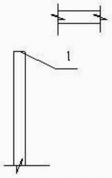
[0026] (1) if figure 1 As shown, according to the common method of pouring and ramming shear walls and columns, the outer wall columns of the shear wall are normally constructed to 550mm below the structural floor, leaving a construction joint 1;

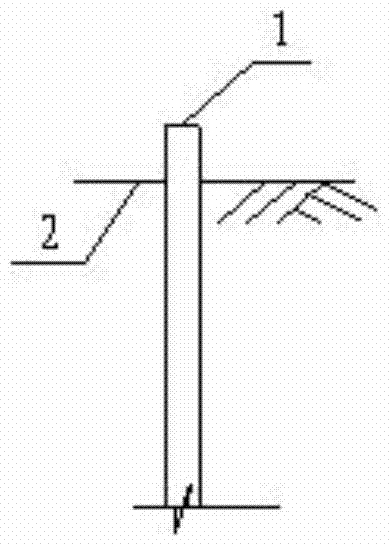
[0027] (2) if figure 2 As shown, the internal and external backfill soil shall be filled to 400 mm below the construction joint 1 of the poured shear wall and column and shall be compacted in time as much as possible;

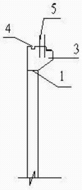
[0028] (3) if image 3 As shown, construct the corbel 3 according to the design size, pay attention to leave the groove 4 and insert the connecting steel bar 5;

[0029] (4) if Figure 4 As shown, in accordance with the normal construction sequence, constru...


PUM


Abstract

A construction method for a basement construction bottom plate includes the following steps that (1) a shear wall and a shear column are normally poured and punned to below the construction bottom plate by 550 mm; (2) inside and outside backfill soil is filled to be below the poured shear wall and the poured shear column by 400 mm and is punned; (3) concrete is poured and punned to construct a bracket, a groove is reserved and an insertion bar is connected normally according to design sizes; (4) an outer wall of the shear wall, the superstructure of the shear column and a coiled material waterproof part of the outer wall are constructed, a coiled material waterproof part is added to a second construction joint, and after a waterproof protection layer of the outer wall is completed, backfill soil is backfilled to the outer wall; (5) after the backfill soil becomes dense and solid within three months under normal circumstances, an under layer of the bottom plate, the coiled material waterproof parts and a protection layer are constructed; (6) bottom plate reinforced concrete is normally constructed; (7) the concrete is maintained, a joint of the construction bottom plate is examined, and if separation occurs, the joint is repaired in a factice caulking mode. The construction technology is simple, the construction period and quality are guaranteed, reworking is avoided, the manufacturing cost is lowered, energy is saved, and the environment is protected.

Description

technical field [0001] The invention relates to a construction method for a basement construction floor, which is used in the construction field. Background technique [0002] The floor and wall construction of the basement has always been an issue of concern in construction. "Code for Quality Acceptance of Underground Waterproofing Engineering" (GB50208-2011) is in Article 5.1.3, and "Building Construction Manual" (Second Edition) is in 13-1-3-10 Construction joints, in 19-5-9-1, point 6, item (2), all clearly require that the horizontal construction joints of the wall should be left at a height not less than 300mm above the bottom surface on the wall. Vertical construction joints should avoid areas with a lot of groundwater and fissure water, and should be combined with deformation joints. For the above requirements, the specific actual situation is sometimes difficult to meet, for example: a project in Liuzhou City, with a construction area of ​​more than 110,000 square...

Claims


Application Information

Patent Timeline
Patent Type & Authority Applications(China)
IPC IPC(8): E02D29/045
Inventor 李毅吕良军覃森潘伟华韦宝娟黄瑞谊黎文东韦元基
Owner GUANGXI METALLURGICAL CONSTR
Why Eureka
Try Eureka