Oil injection pump with centrifugal regulator

A technology of fuel injection pump and adjustment mechanism, which is applied in the direction of fuel injection pump, machine/engine, fuel injection device, etc., can solve the problems of friction and increase of installation length, etc.

Inactive Publication Date: 2014-10-29
STEYR MOTORS GMBH
View PDF6 Cites 4 Cited by
  • Summary
  • Abstract
  • Description
  • Claims
  • Application Information

AI Technical Summary

Problems solved by technology

Here, the centrifugal adjuster does not have a pivotable centrifugal weight but a movable centrifugal weight along an inclined rail, which further increases the installation length and is also subject to friction

Method used


Image

  • Oil injection pump with centrifugal regulator
  • Oil injection pump with centrifugal regulator
  • Oil injection pump with centrifugal regulator

Examples


Embodiment Construction

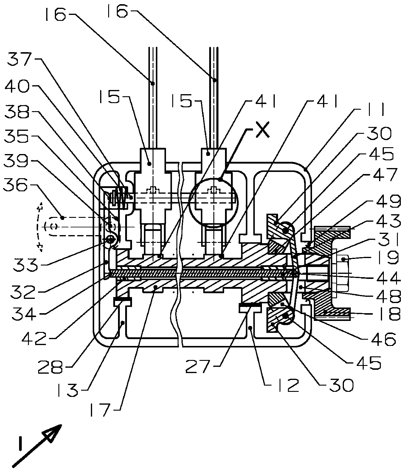
[0016] exist figure 1 The middle represents the fuel injection pump installed in the internal combustion engine (not shown in the figure) represented by the symbol 1. Its housing 11 constitutes a front bearing wall 12 and a rear bearing wall 13 and accommodates a number of pump devices 15 corresponding to the number of cylinders of the internal combustion engine. Fuel injection lines 16 lead from these pump devices 15 to the respective cylinders. It is also possible to have only a single pump device 15 . Mounted in bearings 27 and 28 in bearing walls 12 and 13 is an oil-injected camshaft 17 which extends out of housing 11 over front bearings 27 and at its end fits drive gear 18 . The drive gear 18 is driven by the crankshaft of the internal combustion engine through meshing or through a chain or toothed belt (both not shown in the figure). This is done by fixing the concentric bolt 19 to the injection camshaft 17 .

[0017] The injection camshaft 17 is hollow inside throug...


PUM


Abstract

The present invention relates to an oil injection pump (1), which comprises a shell (11), an oil injection cam shaft (17) rotatably mounted in the shell and driven by a crank of an engine, at least one pump device (15) provided with a regulating rod (37) for regulating the oil injection amount and arranged above or inside the shell (11), and a centrifugal regulator equipped with a centrifugal counterweight (30). For obtaining the oil injection pump which is short in longitudinal direction, simple in structure, and safe in operation, the oil injection cam shaft (17) is hollow and a rod body (31) penetrates through the oil injection cam shaft (17). A lever arm (43) of the centrifugal counterweight (30) acts upon the rod body (31) at one end of the drive side of the rod body (31), the other end (34) of the rod body keeps an effective connection with the regulating rod (37).

Description

technical field [0001] The invention relates to a fuel injection pump, which comprises a casing, a fuel injection camshaft installed in the casing driven by an engine crankshaft rotatably mounted therein, and at least one movable adjustment valve for adjusting the fuel injection quantity. Rod housing-on or housing-mounted pump units and centrifugal adjusters with centrifugal weights mounted on the injection camshaft. This type of fuel injection pump can be used in simple diesel engines, just as it is used in construction machinery, electric generator sets or small cars. Background technique [0002] This type of fuel injection pump is known from the patent document DE3831788A1. In this context, the oil-injected camshaft has two parts. The first part is mounted in the housing, has an injection cam and is driven at its free end. The second portion extends further into the regulator housing. On its free end, a rotating body is suspended, which has a centrifugal weight pivot...

Claims


Application Information

Patent Timeline
Patent Type & Authority Applications(China)
IPC IPC(8): F02M59/44
Inventor 马库斯·伯克斯霍夫迈克尔·阿沙伯
Owner STEYR MOTORS GMBH
Why Eureka
Try Eureka