Deconvolution based radar angle super-resolution imaging method

A technology of super-resolution imaging and radar angle, which is applied in the direction of reflection/re-radiation of radio waves, utilization of re-radiation, measurement devices, etc., which can solve the problems of inability to use angular resolution, distortion of target amplitude information, and position offset.

Active Publication Date: 2014-10-29
UNIV OF ELECTRONICS SCI & TECH OF CHINA
View PDF5 Cites 14 Cited by
  • Summary
  • Abstract
  • Description
  • Claims
  • Application Information

AI Technical Summary

Problems solved by technology

Since the phase information of the signal does not need to be considered in optical imaging, if the convolution inversion method in optics is directly applied to microwave imaging, the phase infor

Method used


Image

  • Deconvolution based radar angle super-resolution imaging method
  • Deconvolution based radar angle super-resolution imaging method
  • Deconvolution based radar angle super-resolution imaging method

Examples


Embodiment Construction

[0069] The present invention uses simulation experiments to demonstrate the feasibility and effectiveness of the proposed radar angle super-resolution method, and all steps and conclusions are verified to be correct on the Matlab2012 simulation platform. The method of the present invention will be further described below in conjunction with the accompanying drawings and specific embodiments.

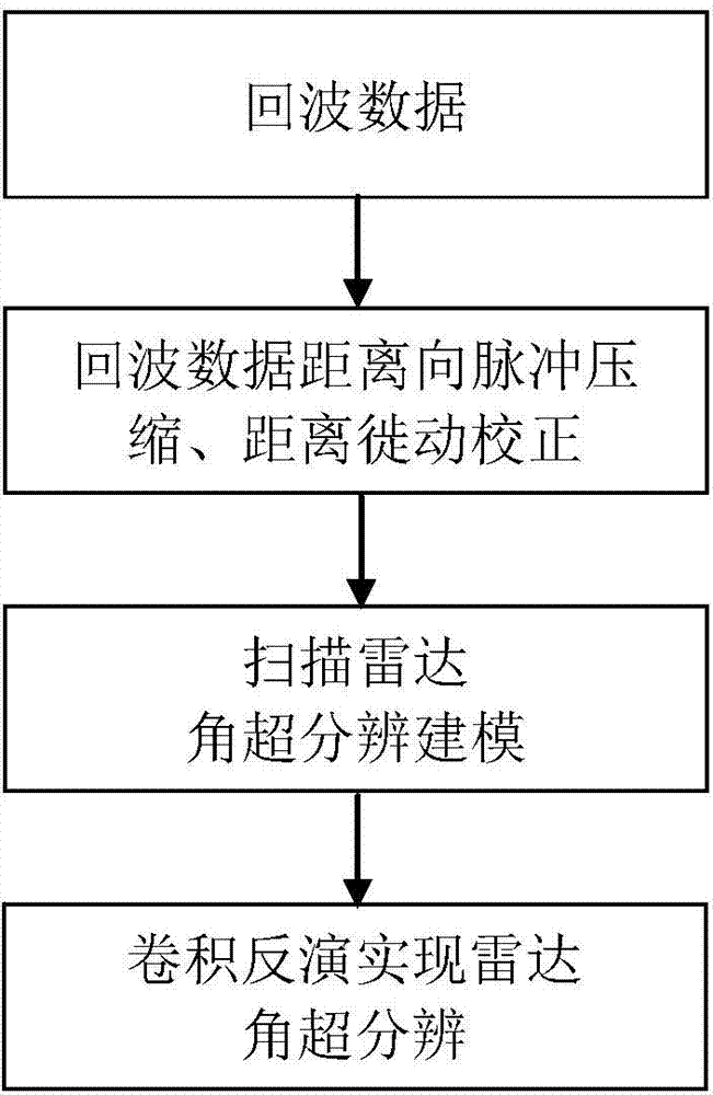
[0070] The schematic flow chart of scanning radar angle super-resolution imaging in the present invention is as follows figure 1 As shown, the specific process is as follows:

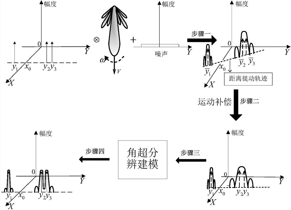
[0071] Step 1: Radar echo modeling,

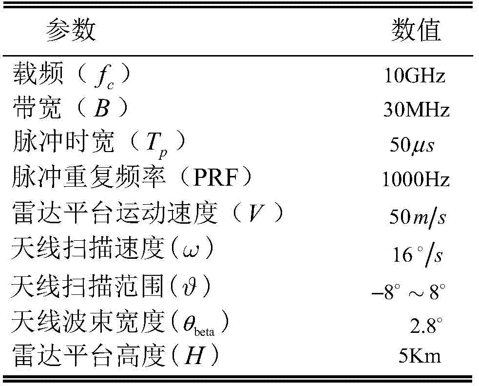
[0072] This implementation is aimed at figure 2 The radar imaging geometric mode shown involves the following relevant parameters: radar platform height H, flight speed V along the positive direction of the X-axis, radar antenna scanning angular velocity ω along the Y-axis direction, radar antenna beam pitch angle θ, and the carrier frequency of the transmitted signal f c...


PUM


Abstract

The invention discloses a deconvolution based radar angle super-resolution imaging method. The deconvolution based radar angle super-resolution imaging method comprises converting the radar angle super-resolution imaging into a convolution inversion problem on a complex domain and adding constraints to change the intrinsic ill-condition of the convolution inversion problem; converting the convolution inversion problem into an implementation problem of an optimal solution of a constraint objective function on a corresponding complex domain; utilizing vectors on a real number domain to represent complex variables and converting the problem of the optimal solution of the constraint objective function on the complex domain into an implementation problem of an optimal solution of an unconstrained objective function on the real number domain; implementing the optimal solution of the unconstrained objective function on the real number domain by a Lagrange method of multipliers and implementing the radar angle scanning super-resolution imaging. According to the deconvolution based radar angle super-resolution imaging method, the limitation of antenna system parameters on the radar image resolution can be broken through, the radar angle super-resolution imaging is implemented, and the effects of the imaging result on the target range, number and position information maintaining are good.

Description

technical field [0001] The invention belongs to the technical field of radar signal processing, in particular to a radar angle super-resolution imaging method based on deconvolution. Background technique [0002] As an important tool in the field of microwave imaging, radar has all-weather and all-weather working capabilities, and has been widely used in marine search and rescue, topographic mapping, geological disaster rescue and other fields. The traditional synthetic aperture radar (SAR) can realize two-dimensional high-resolution imaging in the side-view and oblique front-view areas, but it cannot realize the front-view area imaging of the radar platform. This is because the equidistance lines and iso-Doppler lines in the area of ​​frontal vision are parallel. In order to realize radar forward-looking area imaging, radar forward-looking beam scanning can be used. Scanning radar means that the radar beam scans the detected area uniformly or non-uniformly in azimuth. Thr...

Claims


Application Information

Patent Timeline
IPC IPC(8): G01S13/89
CPCG01S7/285G01S13/89
Inventor 黄钰林李杰包毅邓敏李洁洋查月波杨建宇
Owner UNIV OF ELECTRONICS SCI & TECH OF CHINA
Why Eureka
Try Eureka