Thermomagnetic power generation system driven by thermoacoustic engine

A technology of thermoacoustic engine and power generation system, which can be applied to machines/engines, thermoelectric devices utilizing thermal changes in magnetic permeability, and mechanisms that generate mechanical power, etc. High density, quiet operation

Inactive Publication Date: 2014-10-29
TECHNICAL INST OF PHYSICS & CHEMISTRY - CHINESE ACAD OF SCI
View PDF9 Cites 15 Cited by
  • Summary
  • Abstract
  • Description
  • Claims
  • Application Information

AI Technical Summary

Problems solved by technology

According to the different internal sound fields, thermoacoustic engines can be divided into standing wave type and traveling wave type. The standing wave type is a linear structure, which is simpl

Method used


Image

  • Thermomagnetic power generation system driven by thermoacoustic engine
  • Thermomagnetic power generation system driven by thermoacoustic engine
  • Thermomagnetic power generation system driven by thermoacoustic engine

Examples


Embodiment 1

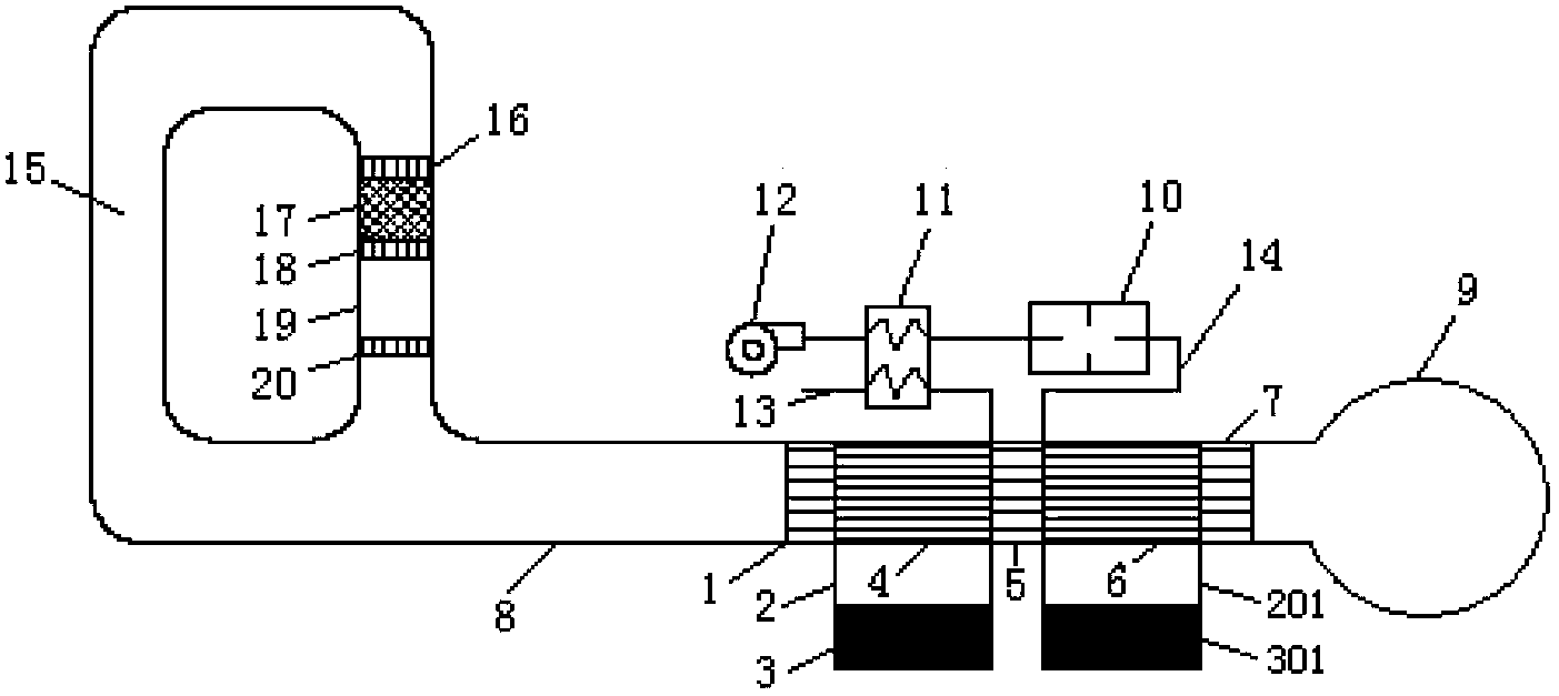
[0037] figure 1 It is a schematic structural diagram of a thermo-magnetic power generation system driven by a thermoacoustic engine (Example 1) of the present invention.

[0038] As can be seen from the figure, its structure includes: a thermoacoustic engine (this embodiment is a traveling wave thermoacoustic engine), a thermomagnetic generator and a gas-fired heat source supply system;

[0039] The traveling wave thermoacoustic engine consists of an annular feedback tube 15, a main room temperature heat exchanger 16, a regenerator 17, a high temperature heat exchanger 18, a thermal buffer tube 19 and a sub room temperature heat exchanger 20 to form a traveling wave circuit; 8 is coupled with the thermomagnetic generator, and finally the resonant cavity 9;

[0040] Described thermomagnetic generator comprises:

[0041] A heat exchange assembly composed of the first room temperature heat exchanger 1, the first soft magnetic section 4, the high temperature heat exchanger 5, t...

Embodiment 2

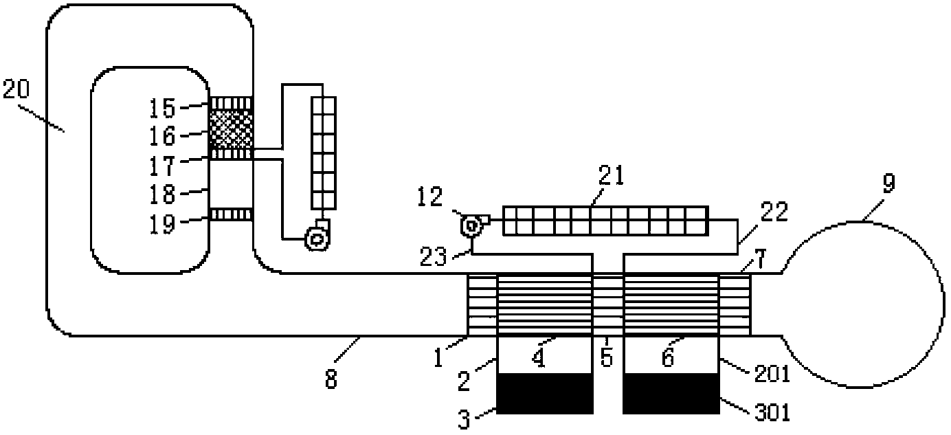
[0053] diagram 2-1 It is a schematic structural diagram of a thermomagnetoelectric power generation system driven by a thermoacoustic engine (Example 2) of the present invention.

[0054] Figure 2-2 for diagram 2-1 Stereoscopic view of the middle trough solar collector.

[0055] In this embodiment, on the basis of Embodiment 1, the gas-type heat source supply system is changed into a trough-type solar heat source supply system, and its structure includes: a traveling wave thermoacoustic engine, a trough-type solar heat source supply system and a thermomagnetic generator.

[0056] The centrally focused parabolic mirror 21 of the trough solar heat source supply system focuses the sunlight on the vacuum heat collecting tube in the middle, the heat transfer oil in the vacuum heat collecting tube is heated, and the water pump 12 drives the heat transfer oil to flow, and enters the high temperature heat exchange along the input pipe 22 Heat exchange with the device 5, and then...

Embodiment 3

[0059] Figure 3-1 It is a schematic structural diagram of a thermomagnetic power generation system driven by a thermoacoustic engine (Example 3) of the present invention.

[0060] Figure 3-2 for Figure 3-1 A perspective view of a mid-dish solar collector.

[0061] In this embodiment, on the basis of Embodiment 1, the gas-fired heat source supply system is changed into a dish-type solar heat source supply system, and its structure includes: a traveling wave thermoacoustic engine, a dish-type solar heat source supply system and a thermomagnetic generator;

[0062] Fresnel lens or parabolic mirror 24 focus sunlight on the receiver in the dish solar heat source supply system, and the high-temperature heat exchanger 5 is just installed on the receiver, so that the high-temperature heat exchanger 5 can be directly heated to a very high temperature. High temperature; at the same time, the collector can also be equipped with an automatic tracking system to change the orientation...


PUM


Abstract

A thermomagnetic power generation system driven by a thermoacoustic engine comprises the thermoacoustic engine, a heat source supply system and a thermomagnetic power generator. The heat source supply system supplies heat for the thermomagnetic power generator; and the thermomagnetic power generator utilizes alternating flow of fluid to converts the heat into electric energy. The thermomagnetic power generator comprises two room temperature heat exchangers; a high temperature heat exchanger arranged between the two room temperature heat exchangers; soft magnets arranged between the room temperature heat exchangers and the high temperature heat exchanger; and two groups of oppositely-arranged bow-type magnetizers. One end of each group of bow-type magnetizer is clamped with a permanent magnet, and the other end is clamped with a soft magnet. The magnetizers are respectively provided with a coil. Each soft magnet, the permanent magnet and a group of bow-type magnetizer form a magnetic loop. When working, the thermoacoustic engine drives the fluid to move back and forth between the room temperature heat exchangers and the high temperature heat exchanger, so that the soft magnets are heated and cooled periodically, the temperature changes around the curie point, the magnetic conductivity changes periodically, the magnetic loop reluctance and magnetic flux change, and the coils generate induced electromotive force to generate electric energy. The thermomagnetic power generation system is noiselessness, wide in applied temperature range and flexible in generated energy adjustment.

Description

technical field [0001] The invention relates to a thermomagnetic power generation device, in particular to a thermoacoustic engine driven thermomagnetic power generation system. Background technique [0002] The thermomagnetic generator is a device that uses a high-permeability soft magnetic material to undergo a huge change in the permeability near the Curie point, thereby causing a change in the magnetic flux passing through the coil in the magnetic circuit, and then generating electrical energy. However, thermomagnetic power generation systems need to alternately heat and cool magnetic materials, and how to achieve rapid heating and cooling of magnetic materials is one of the difficulties in this technology. [0003] Thermomagnetic power generation systems driven by reciprocating piston pumps in the prior art, such as Figure 6 As shown, 1 is the first room temperature heat exchanger, 4 is a soft magnetic body stacked by soft magnetic material sheets, 5 is a high temperat...

Claims


Application Information

Patent Timeline
IPC IPC(8): H01L37/04F03G7/00
Inventor 罗二仓李东辉吴张华
Owner TECHNICAL INST OF PHYSICS & CHEMISTRY - CHINESE ACAD OF SCI
Why Eureka
Try Eureka