
Brake disc body and casting method and device for manufacturing same

A technology of brake disc and disc body, which is applied in the direction of brake disc, manufacturing tools, casting and molding equipment, etc., can solve the problems of casting defects and other problems, and achieve the effect of smooth and balanced mold filling, preventing shrinkage cavities, and improving feeding efficiency.

Active Publication Date: 2014-11-05
CHINA MACHINERY IND PROD +1
View PDF7 Cites 25 Cited by
  • Summary
  • Abstract
  • Description
  • Claims
  • Application Information

AI Technical Summary

Problems solved by technology

[0005] The invention patent with the publication number CN102069148A discloses a casting method for brake discs for high-speed locomotives, which includes the following steps: solidification simulation, sand core design, core box production, core making, core assembly, melting and pouring, box shaking and Cleaning up, the invention adopts the method of combined casting without stacking cores, 4-8 pieces are poured at one time, and the production efficiency is high, but there are still a large number of casting defects in the produced castings
[0006] The utility model patent with the notification number CN202097365U discloses a casting sprue mechanism for automobile brake discs, including a sprue, a runner, a riser and castings, and a slag collecting bag 1 is arranged between the sprue and the runner. And the slag collection bag II, there is a slag collection bag III between the runner and the riser. This utility model is designed with three slag collection channels, which can filter out more than 50% of the slag inclusions in the molten iron, but the castings produced are still There are a large number of casting defects

Method used


Image

  • Brake disc body and casting method and device for manufacturing same
  • Brake disc body and casting method and device for manufacturing same
  • Brake disc body and casting method and device for manufacturing same

Examples


Embodiment 1

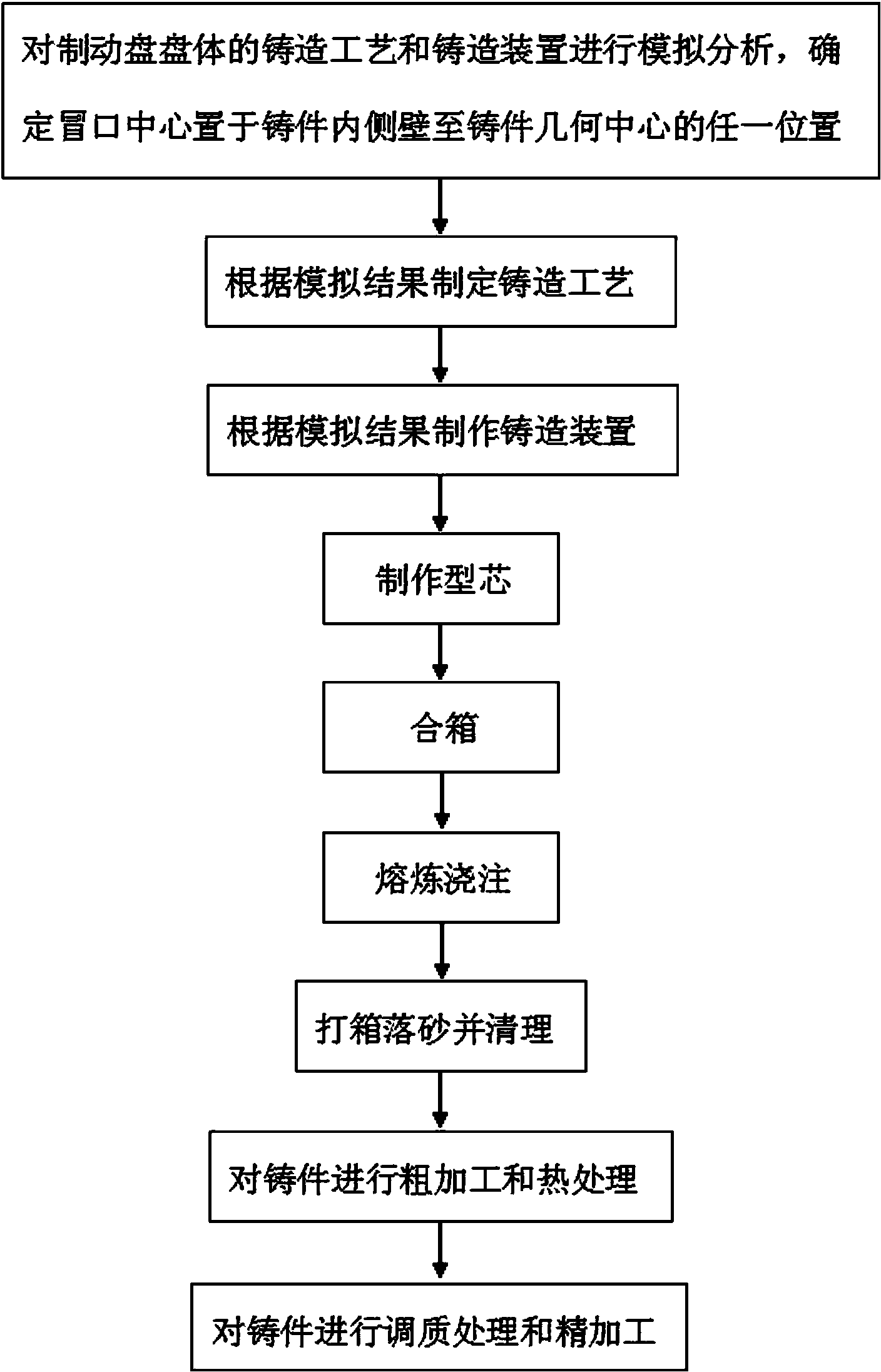
[0068] Taking the high-speed train cast steel brake disc body (with an outer diameter of 600mm and an inner diameter of 240mm) as an example, the casting process is as follows: figure 1 As shown, it includes the following steps in sequence:

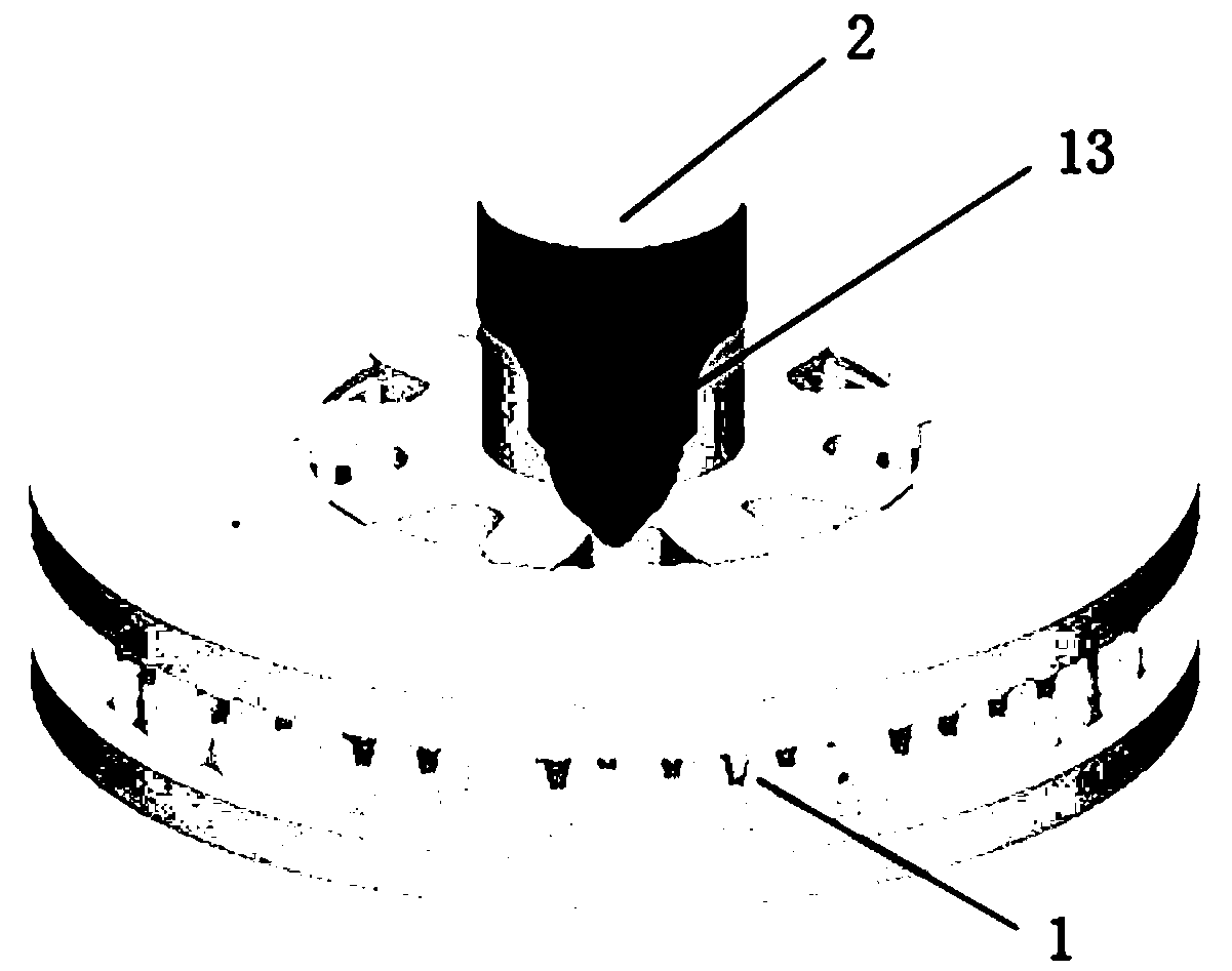
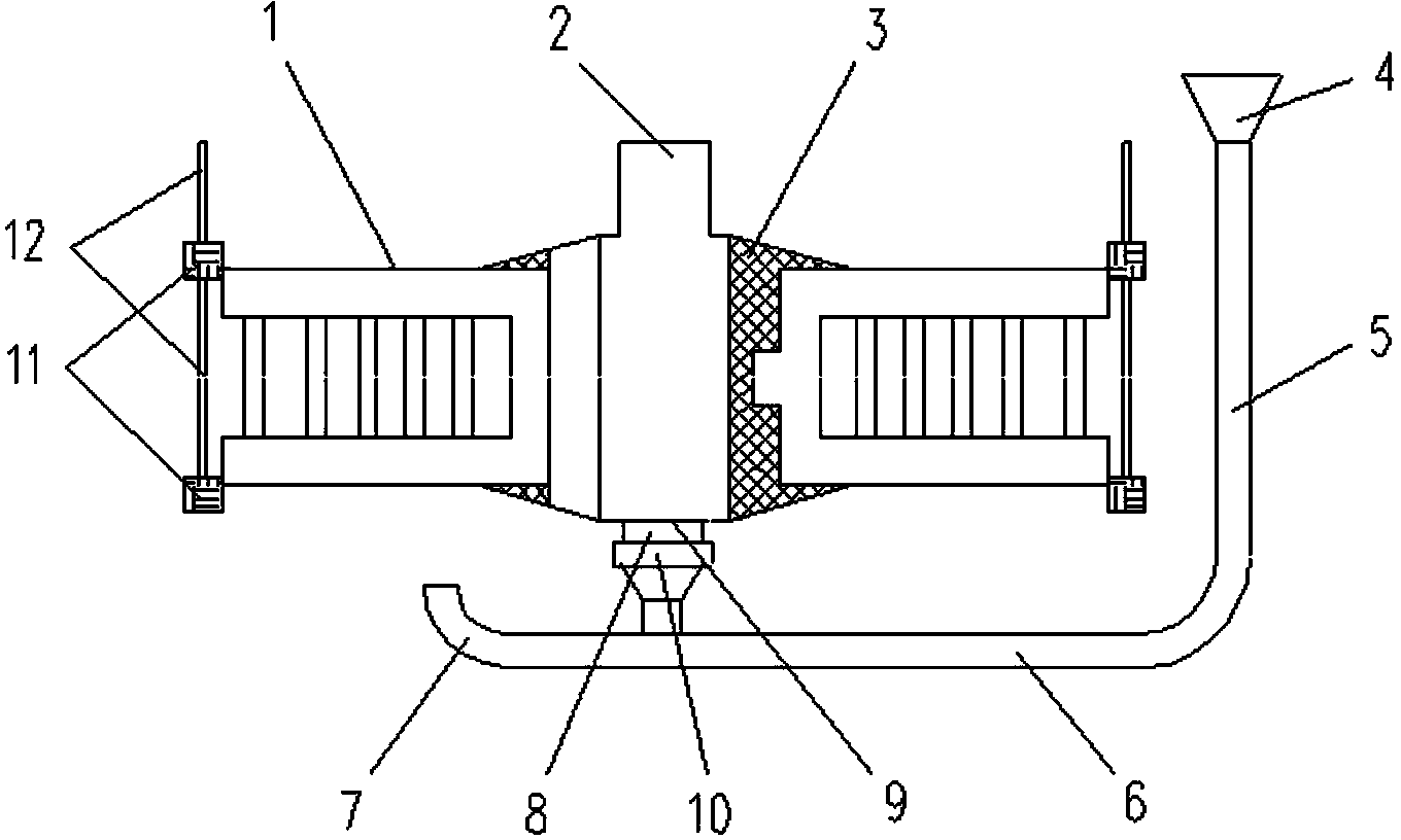
[0069] (1) Use computer simulation software to simulate and analyze the casting process and casting device of the brake disc body, determine the positions of the gating system and the feeding system, and place the center of the riser 2 of the feeding system at the geometric center of the casting 1;

[0070] (2) According to the simulation analysis results of step (1), the casting process of the brake disc body is formulated, and the bottom pouring is carried out by introducing molten metal at the bottom, wherein the molten metal enters the cavity from the bottom of the rectifying and filtering device 10;

[0071] (3) Make the casting device, and the positions of the gating system and the feeding system conform to the results of the si...

Embodiment 2

[0089]Taking the high-speed train cast steel brake disc body (with an outer diameter of 610 mm and an inner diameter of 240 mm) as an example, the casting process is as follows: figure 1 As shown, it includes the following steps in sequence:

[0090] (1) Use computer simulation software to simulate and analyze the casting process and casting device of the brake disc body, determine the positions of the gating system and the feeding system, and place the center of the riser 2 of the feeding system at the geometric center of the casting 1;

[0091] (2) According to the simulation analysis results of step (1), the casting process of the brake disc body is formulated, and the bottom pouring is carried out by introducing molten metal at the bottom, wherein the molten metal enters the cavity from the bottom of the rectifying and filtering device 10;

[0092] (3) Make the casting device, and the positions of the gating system and the feeding system conform to the results of the simul...

Embodiment 3

[0109] Taking the high-speed train cast steel brake disc body (with an outer diameter of 610 mm and an inner diameter of 250 mm) as an example, the casting method and casting device are basically the same as those in the first embodiment.

[0110] The Magma simulation software is selected for simulation analysis, and it is determined that the center of the riser 2 of the feeding system is placed at a position 10mm away from the geometric center of the casting 1. The number of the riser 2 is one, the shape is a cylinder, the diameter is 145mm, and the height is 145mm. The bottom of the riser 2 corresponds to an ingate 9, and the center of the riser 2 and the center of the ingate 9 are both placed at a position 10 mm away from the geometric center of the casting 1. The flow velocity of the molten metal in the gate 9 is 30cm / s; the rising velocity of the molten metal in the casting 1 is 17mm / s.

[0111] Sprue cup 4, sprue 5, runner 6 and runner overflow section 7 are all mad...


PUM

PropertyMeasurementUnit
yield strengthaaaaaaaaaa
diameteraaaaaaaaaa

Abstract

The invention discloses a brake disc body and a casting method and device for manufacturing the same. The method comprises the following steps: firstly performing simulation analysis on a casting process and the casting device of the brake disc body by computer simulation software to determine the positions of a pouring system and a feeding system, wherein the center of a riser of the feeding system is located at any position from the inner sidewall of a cast piece to the geometrical center of the cast piece; and performing bottom pouring in a manner of introducing metal liquid from the bottom, wherein the metal liquid enters a cavity from the bottom of a rectifier filter device. The casting device and the casting method of the brake disc body disclosed by the invention can be used for performing sequential condensation and complete feeding on the cast piece, effectively preventing defects of shrinkage cavities, shrinkage porosity, sand holes, air holes, slag blowholes, cracks and the like, guaranteeing the performance isotropy of the cast piece and guaranteeing the production of the high-quality brake disc body.

Description

technical field [0001] The invention relates to a casting method, in particular to a casting method and device suitable for a high-speed train cast steel brake disc body, and the brake disc body produced thereby. Background technique [0002] Brake discs are key components of high-speed trains and play an important role in train braking. Due to its complex and harsh working environment, it is inconvenient to maintain and replace. It is required that brake disc products must have stable quality and long service life. [0003] A large number of studies have shown that under the condition of a certain material, the main reason for the failure of the cast brake disc body is the casting defects such as shrinkage cavity, shrinkage porosity, sand hole and crack in the disc body. [0004] High-speed trains with a speed of more than 250km / h put forward higher requirements on the quality of the brake disc body, and the tolerance for casting defects such as shrinkage cavities, shrink...

Claims


Application Information

Patent Timeline
Patent Type & Authority Applications(China)
IPC IPC(8): B22C9/08B22C9/22F16D65/12
Inventor 安朝阳
Owner CHINA MACHINERY IND PROD
Learn More