Ion film-plating device and ion film-plating method

A technology of ion coating and magnetron sputtering, applied in ion implantation coating, sputtering coating, vacuum evaporation coating, etc., can solve the problems of unstable discharge, low deposition rate, difficulty in obtaining beam current, etc., and achieve The effect of increasing the beam current density and increasing the deposition rate

Active Publication Date: 2014-11-05
PEKING UNIV SHENZHEN GRADUATE SCHOOL
View PDF6 Cites 12 Cited by
  • Summary
  • Abstract
  • Description
  • Claims
  • Application Information

AI Technical Summary

Problems solved by technology

However, according to an article by Anders, this technology works in the abnormal glow discharge stage close to arc discharge, and it is easy to transition to arc discharge to produce "arcing", the discharge is unstable, and for different target materials, the deposited particles are ionized The rate difference is large, it is difficult to obtain 100% ionized beam current (A.Anders.High power impulse magnetron sputtering: Current-voltage-time characteristic indicate the onset

Method used


Image

  • Ion film-plating device and ion film-plating method
  • Ion film-plating device and ion film-plating method
  • Ion film-plating device and ion film-plating method

Examples


Embodiment

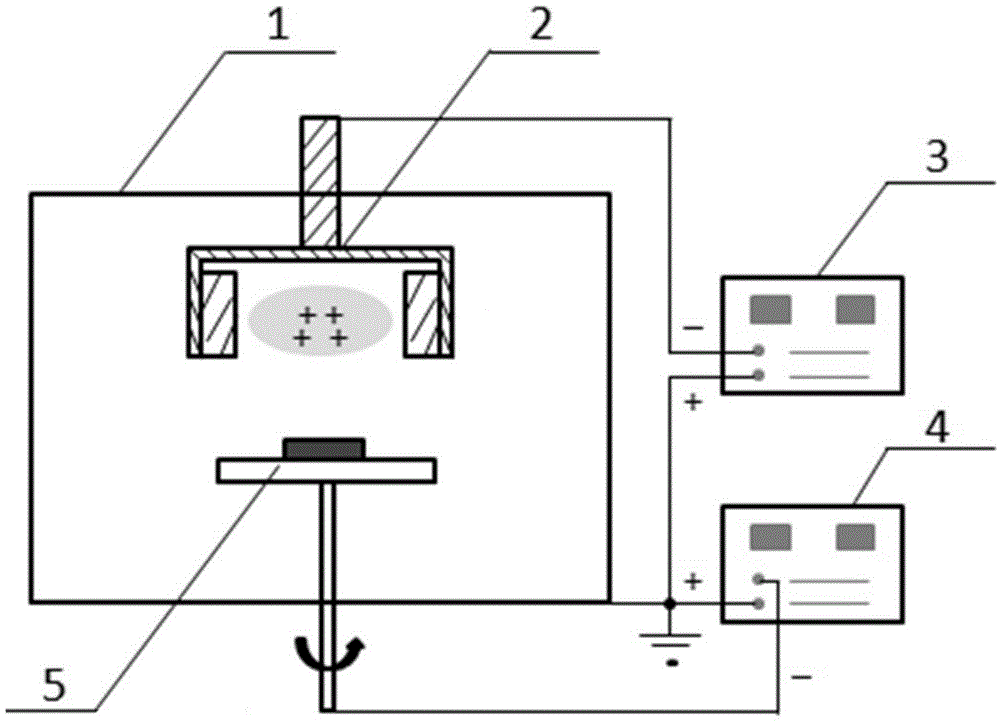
[0027] The ion plating device of this example, such as figure 1 As shown, it includes a vacuum chamber 1, a magnetron sputtering target source 2, a high-power pulse magnetron sputtering power supply 3, a bias power supply 4 and a workpiece platform 5; the vacuum chamber 1 is a closed cavity, and the magnetron sputtering target source 2 and the workpiece platform 5 are arranged in the vacuum chamber 1, and the magnetron sputtering target source 2 is located directly opposite the workpiece platform 5; the high-power pulse magnetron sputtering power supply 3 and the bias power supply 4 are arranged outside the vacuum chamber 1, and the high-power pulse The negative pole of the magnetron sputtering power supply 3 is electrically connected to the magnetron sputtering target source 2, and the positive pole is grounded. The negative pole of the bias power supply 4 is electrically connected to the workpiece platform 5, and the positive pole is grounded.

[0028] Among them, this examp...


PUM


Abstract

The invention discloses an ion film-plating device and an ion film-plating method. In the ion film-plating device, a magnetic-control target is designed into a cylinder shape, all sputtering is completed inside the cylindrical target source, a bias power supply is adopted to lead out an ion beam flow to be deposited on a workpiece, therefore, ions which are electrically neutral or are not ionized cannot be attracted out by an electric field, and thus ion deposition can achieve 100%. In addition, as sputtering of the magnetic-control sputtering target source is carried out in the cylinder, even through arcing is generated, generation is carried out just inside the cylinder, and the film plated workpiece cannot be affected, and the arcing is avoided from affecting film plating. Furthermore, the target source ions are led out of the cylinder by the bias power supply, target voltage attraction on the ions after leading out is weakened, and at the same time, the area of the led-out beam flow is far smaller than the target surface area, so that the led-out beam flow density is greatly improved, and the deposition rate is effectively improved.

Description

technical field [0001] The present application relates to the field of ion plating, in particular to an ion plating device and an ion plating method. Background technique [0002] Plasma surface treatment and coating technology has been widely used in industrial engineering fields such as tools, molds, and mechanical protection, as well as in daily life such as thin-film solar cells, lithium batteries, and mobile phones, watches, and lighting. As far as industrial coatings are concerned, in 2007, Balzers Coatings estimated based on its sales data and market research data in China that the total PVD coating market in China was about RMB 400-500 million in 2007. The potential is about 800-100 million RMB, and the data is growing rapidly at a rate of 10%-20% per year. [0003] At present, there are two most widely used plasma coating technologies, magnetron sputtering and cathodic arc ion plating. These two technologies have their own advantages and disadvantages. The deposit...

Claims


Application Information

Patent Timeline
IPC IPC(8): C23C14/35
Inventor 吴忠振潘锋
Owner PEKING UNIV SHENZHEN GRADUATE SCHOOL
Why Eureka
Try Eureka