
Magnetic mirror field constrained bitarget non balancing magnetron sputtering method

A magnetron sputtering and unbalanced technology, applied in the field of surface engineering, can solve the problems of low plasma density, small adjustment range, and reduced plasma density, so as to improve sputtering efficiency, improve film quality, and strengthen ionization effect Effect

Inactive Publication Date: 2007-04-18
DALIAN UNIV OF TECH
View PDF0 Cites 6 Cited by
  • Summary
  • Abstract
  • Description
  • Claims
  • Application Information

AI Technical Summary

Problems solved by technology

"Development and Status of Sputtering Deposition Technology" ("Journal of Vacuum Science and Technology" Vol.25, No.3, 2005) and "Progress and Application of Magnetron Sputtering Technology" ("Modern Instruments" No.5, 2005) The development and application of various magnetron sputtering deposition technologies are introduced. In ordinary magnetron sputtering devices, the plasma is confined by the magnetic field on the surface of the cathode. The density of the plasma in the deposition area is very low, and it is difficult to obtain an ideal plasma. state, the energy of the deposited particles is around a few electron volts, and the density of the plasma is further reduced sharply at 30-50 mm in front of the magnetron sputtering target
Due to the lack of ion bombardment, the deposited film has a large number of defects and stresses, which affects the performance of the film. Since the magnetic field structure of the magnetron sputtering device is an open space structure, the parameters can be adjusted in a small range
The current magnetron sputtering deposition technology has the technical shortcomings mentioned above. In order to solve these technical shortcomings, researchers have developed an unbalanced magnetron sputtering system with closed and magnetic fields. Although this unbalanced magnetron sputtering system has a magnetic field The magnetic field lines, but the permanent magnet is basically used as the magnetic field source, the permanent magnet forms the magnetic circuit for enhancing the discharge on the surface of the cathode, and also serves as the magnetic circuit for confining the plasma, but the problem with this structure is that the two functions of the permanent magnet cannot be At the same time, the best matching effect can be achieved, the parameters cannot be adjusted, and the sealing is not good. The unbalanced magnetic field in the ordinary closed-field unbalanced sputtering system is not completely closed, and the adjustment range of the deposition parameters is small. The degree of restraint is not ideal. One of the important problems is that the closed-field unbalanced sputtering system announced in the current literature always has a loophole in the magnetic field, which destroys the closure of the closed magnetic field. End of closed unbalanced sputtering target

Method used


Image

  • Magnetic mirror field constrained bitarget non balancing magnetron sputtering method
  • Magnetic mirror field constrained bitarget non balancing magnetron sputtering method
  • Magnetic mirror field constrained bitarget non balancing magnetron sputtering method

Examples


Embodiment Construction

[0014] The specific embodiments of the present invention will be described in detail below in conjunction with the technical solutions and accompanying drawings.

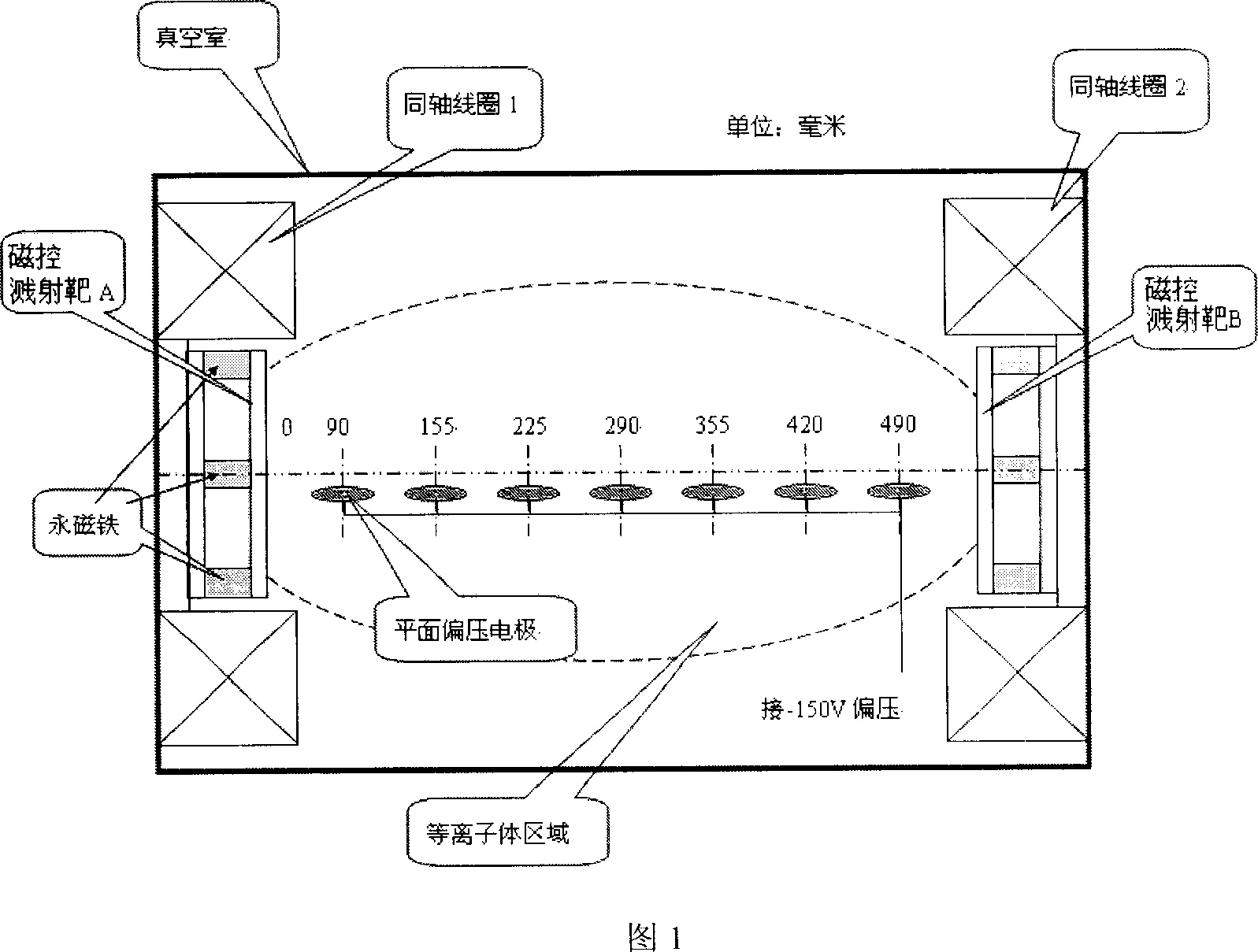
[0015] A magnetic mirror field-constrained double-target unbalanced magnetron sputtering method uses two permanent magnet magnetron sputtering targets A and magnetron sputtering targets B to be placed oppositely, and two coaxial coils 1 and 2 It is two Helmholtz coils, coaxially placed on the periphery of magnetron sputtering target A and magnetron sputtering target B, two oppositely placed permanent magnet magnetron sputtering targets A and magnetron sputtering targets B The two Helmholtz coaxial coils 1 and 2 coaxially placed around form a magnetic mirror field after the current is applied. During the application process, the permanent magnet magnetron sputtering target A and the magnetron sputtering target B The internal permanent magnet forms a closed magnetic field on the surface of the magnetron sputtering tar...


PUM

PropertyMeasurementUnit
diameteraaaaaaaaaa

Abstract

The invention discloses a opposite-target non-equilibrium magnetron spattering system with magnetic mirror field restriction, which is mainly used in technique field of surfacial project. It is characterized in that: Two electrified coaxial coils are set opposite two permanent-magnet magnetron targets. They can form a complete closed magnetic mirror field which is coaxial with magnetron targets. To control magnetic mirror field based on regulating current in coils, and adjust state, deposit parameter of discharging plasma subtly. Magnetic coils enhance cathode discharging, increase plasma derivation in cathode zone and advance plasma density in deposit zone. Applying coaxial magnetic mirror field to restrain plasma with adding coaxial coils can enlarge adjusting range of deposit parameter. Compared with routine magnetron spattering technique, non-equilibrium magnetron spattering technique has adjustable plasma state, high plasma leaving rate and high ion-atom arrival rate etc.

Description

technical field [0001] The invention belongs to the technical field of surface engineering, and in particular relates to a method for unbalanced magnetron sputtering with two targets constrained by a magnetic mirror field. A pair of opposite unbalanced magnetron sputtering targets with coaxial coils attached can be used in a larger Increase the density of the plasma in the deposition area and adjust the deposition parameters within a range. Background technique [0002] Magnetron sputtering deposition technology is used for material modification and film deposition in the field of surface engineering. In ordinary magnetron sputtering devices, a closed magnetic field on the surface of the cathode is used to generate plasma, in which ions bombard the cathode material under the action of the cathode voltage to form Sputtering effect, the formed deposition material ions and atoms diffuse to the surface of the workpiece to be plated to form a thin film. During the film deposition...

Claims


Application Information

Patent Timeline
Patent Type & Authority Applications(China)
IPC IPC(8): C23C14/35C23C14/34
Inventor 牟宗信贾莉李国卿赵华玉刘升光
Owner DALIAN UNIV OF TECH
Learn More