Broadband high-efficiency and high-directionality electrically small antenna

A high-directivity, electrically small antenna technology, applied to antennas, electrical components, radiating elements, etc., to achieve the effects of expanding working bandwidth, easy manufacturing, and improving directivity

Active Publication Date: 2014-11-05
SUNWAVE COMM
View PDF5 Cites 22 Cited by
  • Summary
  • Abstract
  • Description
  • Claims
  • Application Information

AI Technical Summary

Problems solved by technology

It can be seen that the design of an antenna that is electrically small, broadband, high-efficiency, and directional radiation is extremely challenging

Method used


Image

  • Broadband high-efficiency and high-directionality electrically small antenna
  • Broadband high-efficiency and high-directionality electrically small antenna
  • Broadband high-efficiency and high-directionality electrically small antenna

Examples


Embodiment Construction

[0025] The preferred embodiments of the present invention will be described in detail below with reference to the accompanying drawings.

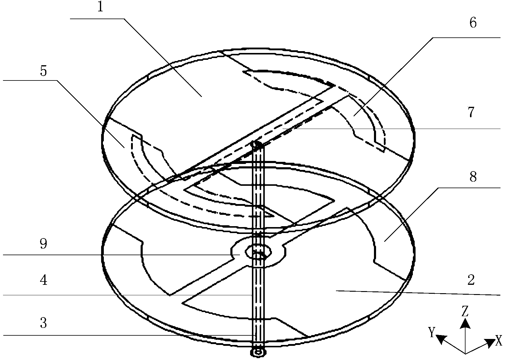
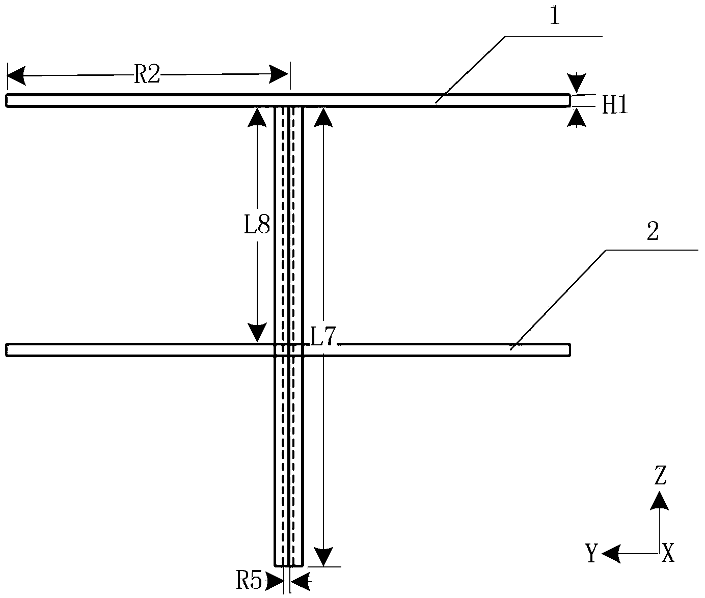
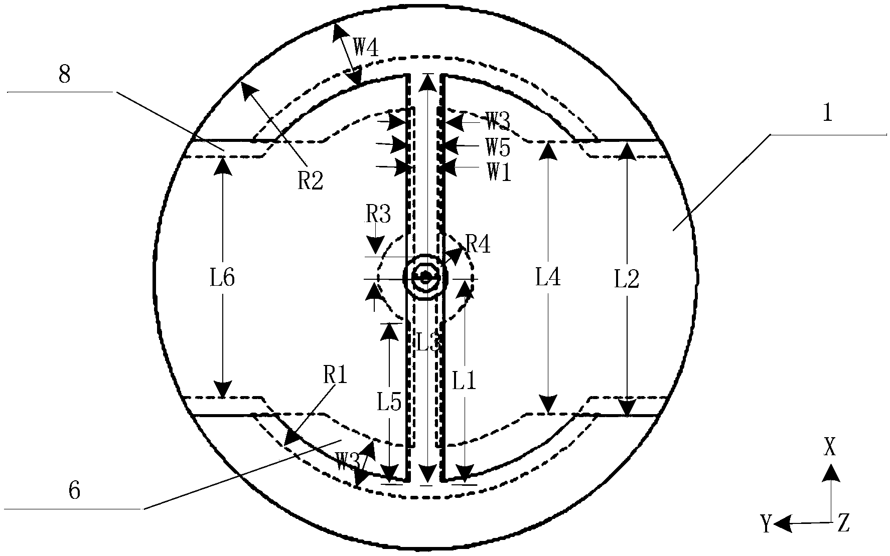
[0026] The overall structure diagram, front view, top view, and side view of the broadband high-efficiency high-directivity electric small antenna described in the present invention are respectively as follows figure 1 , figure 2 , image 3 , Figure 4 shown. The antenna includes an excitation unit 6 , an upper parasitic unit 5 , a lower parasitic unit 8 , an upper thin cylindrical dielectric plate 1 , a lower thin cylindrical dielectric plate 2 , a coaxial feeder inner conductor 3 , and a coaxial feeder outer conductor 4 . The thickness of the two thin cylindrical dielectric plates is denoted as H1, the material RogersDuroid6010 is used, the dielectric constant is 10.2, the relative magnetic permeability is 1.0, and the loss tangent is 0.0023. The metal sheets of the excitation unit, the upper parasitic unit and the lower parasitic un...


PUM


Abstract

The invention relates to a broadband high-efficiency and high-directionality electrically small antenna, and belongs to the technical field of antennae. The antenna comprises an exciting unit, an upper parasitic unit, a lower parasitic unit, two thin cylindrical dielectric slabs and a coaxial feeder. The radii of the two thin cylindrical dielectric slabs are the same, the centers of the two thin cylindrical dielectric slabs are aligned, and the two thin cylindrical dielectric slabs are parallel in the vertical direction. The exciting unit and the upper parasitic unit are arranged on the bottom surface and the top surface of the upper thin cylindrical dielectric slab respectively, and the lower parasitic unit is arranged on the top surface of the lower thin cylindrical dielectric slab. An inner conductor and an outer conductor of the coaxial feeder are connected with two metal sheets of the existing unit respectively, and the feed end of the coaxial feeder penetrates through the lower thin cylindrical dielectric slab, extends to the lower side of the lower thin cylindrical dielectric slab by a certain distance and is connected with a 50 omega signal source. The antenna is simple in design, compact in structure and easy to manufacture and can be applied to broadband wireless communication systems with the operating frequency being 1 GHz or so.

Description

technical field [0001] The invention belongs to the technical field of antennas, and relates to a broadband, high-efficiency, and high-directivity electrically small antenna. Background technique [0002] As wireless communication radio frequency front-end equipment continues to advance towards miniaturization, compactness, integration, and multi-function, more and more stringent requirements are put forward for the design of electrically small antennas. In recent years, with the continuous deepening of research, antenna workers try to reduce the overall electrical size of the antenna as much as possible, so as to reach the limit level of physical structure design, and maintain good radiation performance, and have achieved certain research results. First of all, in terms of antenna miniaturization and multi-functional design, currently more popular technologies include: improvement and optimization of its own physical structure, such as slotting and bending antenna; loading ...

Claims


Application Information

Patent Timeline
Patent Type & Authority Applications(China)
IPC IPC(8): H01Q1/36H01Q15/14H01Q19/30
Inventor 唐明春理查德·齐奥尔科夫斯基
Owner SUNWAVE COMM
Why Eureka
Try Eureka