Decoupling Test Device for Centrifugal Pumps

A test device, a technology for centrifugal pumps, applied in pump control, non-variable-capacity pumps, machines/engines, etc., can solve problems such as inability to reduce vibration and noise, difficulty in quantitative identification of excitation sources, and inability to separate excitation sources. The connection structure is optimized to reduce the effect of vibration transmission

Active Publication Date: 2016-04-13
SHANGHAI MARINE EQUIP RES INST +1
View PDF9 Cites 1 Cited by
  • Summary
  • Abstract
  • Description
  • Claims
  • Application Information

AI Technical Summary

Problems solved by technology

[0006] (1) The vibration and noise generated by fluid excitation, mechanical excitation and electromagnetic excitation are coupled with each other. The vibration and noise response of the electric centrifugal pump unit is the aliasing coupling effect of each excitation source, and the separation of the excitation sources cannot be realized. This makes the quantitative identification of the excitation source difficult. It brings great difficulty, and it is impossible to achieve a directional vibration and noise reduction design for different excitation characteristics of centrifugal pumps;
[0007] (2) Under the existing centrifugal pump structure, the volute and the motor are rigidly connected, and it is impossible to complete the experimental research on the influence of single factor changes such as volute profile design, volute processing materials and processing technology on the vibration and noise of electric centrifugal pumps

Method used


Image

  • Decoupling Test Device for Centrifugal Pumps
  • Decoupling Test Device for Centrifugal Pumps
  • Decoupling Test Device for Centrifugal Pumps

Examples


Embodiment Construction

[0030] The present invention will be further described below in conjunction with the accompanying drawings and embodiments.

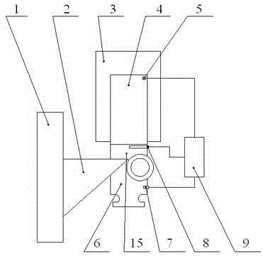
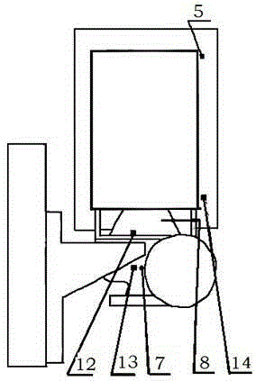
[0031] like figure 1 , As shown in 2, a decoupling test device for a centrifugal pump is mainly composed of a decoupling system, a support system, a water pump system, a drive system, and a test system.

[0032] The decoupling system consists of separate decoupling brackets 2. The support system is composed of a volute support base 1 and a motor support base 3, and the water pump system 6 is composed of impellers, volutes and other components of the centrifugal pump. The drive system is made up of drive motor 4. The test system is composed of an acceleration sensor, a wireless stress and strain sensor 15, a dynamic pressure pulsation sensor 7, an eddy current sensor 8, and a signal acquisition and data analysis device 9, etc.

[0033] The volute is installed on the volute support base 1 by separating the decoupling bracket 2, the impeller rotor is in...


PUM


Abstract

The invention relates to a decoupling testing device for a centrifugal pump. A spiral casing of the centrifugal pump is arranged on a spiral casing support pedestal through a separation decoupling bracket, an impeller rotor is arranged on a motor shaft of a driving motor of the centrifugal pump, and the driving motor of the centrifugal pump is arranged on a motor support pedestal which is independent of the spiral casing support pedestal, so that the spiral casing is physically separated from a rotor of the driving motor to realize the vibration decoupling of fluid excitation, mechanical excitation and electromagnetic excitation; a dynamic pressure pulsation sensor and a vibration acceleration sensor are arranged on the spiral casing, an eddy current sensor is arranged at the impeller rotor, a wireless stress-strain sensor is arranged on a blade, vibration acceleration sensors are arranged at bearings and legs of the motor, are connected with an acquisition and data analysis device, and are used for acquiring vibration transmission characteristics of a fluid excitation source to analyze quantitative characteristics of the fluid excitation source and realize the directional vibration and noise reduction design according to the quantitative characteristics of the fluid excitation source.

Description

technical field [0001] The invention relates to a centrifugal pump test device, in particular to a centrifugal pump decoupling test device. Background technique [0002] A centrifugal pump is a general-purpose fluid machine that converts the mechanical energy of the prime mover into the pressure energy and kinetic energy of the conveyed liquid. Reducing the vibration and noise of the centrifugal pump not only helps to prolong its service life, but also improves the working environment of the equipment and its surrounding life. environment. [0003] The excitation source that causes the vibration and noise of the centrifugal pump is mainly composed of three aspects: fluid excitation, mechanical excitation and electromagnetic excitation. The vibration and noise of the pump volute and impeller are transmitted to the machine base. It is related to the fluid flow condition of the flow field in the centrifugal pump. The main factors affecting the fluid flow condition of the flow ...

Claims


Application Information

Patent Timeline
Patent Type & Authority Patents(China)
IPC IPC(8): F04D15/00
Inventor 李国平王强陈长盛柳瑞锋周相荣代学昌马振来
Owner SHANGHAI MARINE EQUIP RES INST
Why Eureka
Try Eureka