Voltage-controlled oscillator

A technology of voltage-controlled oscillator and voltage-controlled oscillator circuit is applied in the direction of automatic power control, electrical components, etc. Current utilization, power saving effect

Active Publication Date: 2014-11-12
TSINGHUA UNIV
View PDF3 Cites 13 Cited by
  • Summary
  • Abstract
  • Description
  • Claims
  • Application Information

AI Technical Summary

Problems solved by technology

Although a lot of research has been carried out on Class-C voltage-controlled oscillators in academia and industry and some achievements have been made, these Class-C voltage-controlled oscillators still have trade-offs in power consumption and phase noise and wide coverage, etc. many problems

Method used


Image

  • Voltage-controlled oscillator
  • Voltage-controlled oscillator
  • Voltage-controlled oscillator

Examples


Embodiment 1

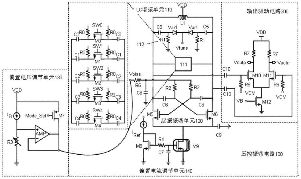
[0049] figure 1 It is a schematic diagram of the composition of the voltage controlled oscillator in the first embodiment of the present invention. From figure 1 It can be seen that the voltage-controlled oscillator mainly consists of a voltage-controlled oscillation circuit 100 and an output drive circuit 200. Among them, the voltage controlled oscillation circuit 100 is divided into an LC resonance unit 110, a vibrating oscillation unit 120, a bias voltage adjustment unit 130, and a bias current adjustment unit 140 according to functions.

[0050] The LC resonance unit 110 adopts a differential structure, and is composed of a differential inductor L1, capacitors C0-C5, resistors R0-R1, transistors M0-M4 and a varactor diode Var1. Among them, the middle tap of the differential inductor L1 is connected to the DC voltage VDD, and the two ends of the differential inductor L1 are connected in parallel with a capacitor array module 111 composed of capacitors C0-C4, transistors M0-M4 ...

Embodiment 2

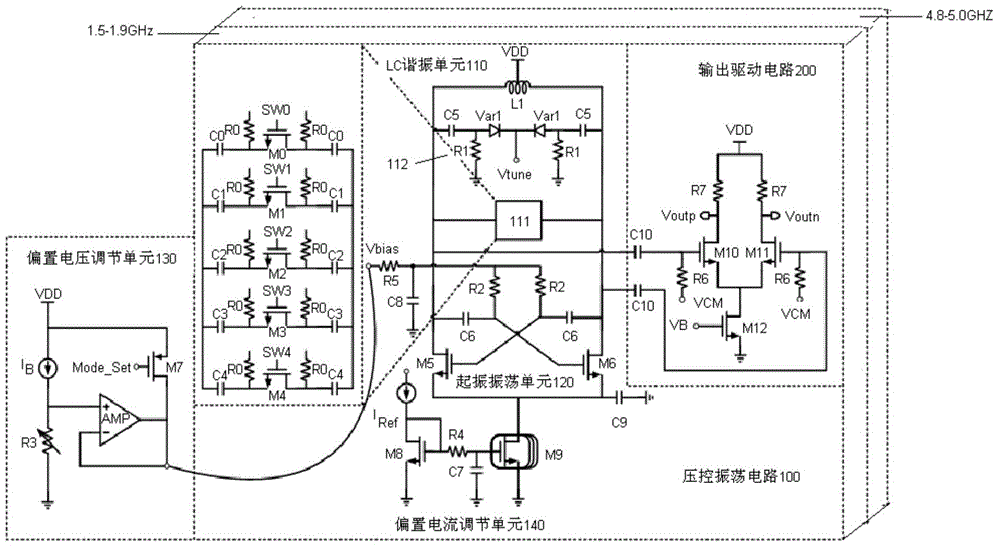
[0086] In order to meet the requirements of wide frequency coverage, the present invention also provides a method such as figure 2 The dual-band voltage-controlled oscillator shown. The dual-band voltage-controlled oscillator is composed of a voltage-controlled oscillator working at 1.5-1.9GHz and a voltage-controlled oscillator working at 4.8-5GHz in parallel, and the two voltage-controlled oscillators can share a bias voltage adjustment unit . This dual-band voltage-controlled oscillator can cover commonly used RF frequency bands, and can optimize power consumption and phase noise through flexible configuration in different application scenarios, and is particularly suitable for low-power RF transceivers supporting multiple Wi-Fi protocols Machine chip.


PUM


Abstract

The invention relates to a voltage-controlled oscillator which comprises a voltage-controlled oscillating circuit. The voltage-controlled oscillating circuit comprises an LC resonance unit, an oscillation-starting oscillating unit and a bias voltage adjustment unit. The oscillation-starting oscillating unit comprises a first transistor and a second transistor which are in cross coupling, the drain of the first transistor and the drain of the second transistor are connected with the two ends of a differential inductor of the LC resonance unit respectively, the voltage of the drains is changed along with changes of the same bias voltage, and the sources receive the same bias current. The bias voltage adjustment unit provides the bias voltage to the oscillation-starting oscillating unit and adjusts the bias voltage to enable conductive angles of the first transistor and the second transistor to be changed from 0 degree to 180 degrees, and therefore the LC resonance unit starts to oscillate in a CLASS-AB mode and oscillates in a CLASS-C mode. In addition, the voltage-controlled oscillating circuit is provided with a bias current adjustment unit, and the bias current adjustment unit provides the bias current to the oscillation-starting oscillating unit to achieve power dissipation configuration and phase noise configuration.

Description

Technical field [0001] The invention relates to a voltage-controlled oscillator for a radio frequency chip, in particular to a voltage-controlled oscillator that is easy to start-up and has low power consumption. Background technique [0002] Since the Wi-Fi frequency band does not require any telecom operation license worldwide, WLAN wireless equipment provides a wireless air interface that can be used worldwide, with extremely low cost and extremely high data bandwidth. In recent years, as Wi-Fi coverage has become wider and wider, people have become more and more concerned about them. Users can not only realize Bluetooth transmission, high-definition video transmission, and wireless video monitoring in the Wi-Fi coverage area, but also can perform medical, smart home and other applications. Currently, Wi-Fi has many frequency bands, such as 2.4-2.5GHz worldwide, 902-928MHz in the United States, 863-868MHz in Europe, 755-787MHz in China, and 950-968MHz in Japan. Faced with a ...

Claims


Application Information

Patent Timeline
Patent Type & Authority Applications(China)
IPC IPC(8): H03L7/099
Inventor 池保勇韩思扬张泽宏王志华
Owner TSINGHUA UNIV
Why Eureka
Try Eureka