
Thermal image monitoring device, thermal image monitoring system and thermal image monitoring method

A monitoring device and information configuration technology, which can be applied to measurement devices, closed-circuit television systems, radiation pyrometry, etc., can solve the problems of increased workload, large monitoring workload, and sudden omission, and reduce labor intensity. , Reduce system cost, use simple effect

Inactive Publication Date:
View PDF7 Cites 4 Cited by
  • Summary
  • Abstract
  • Description
  • Claims
  • Application Information

AI Technical Summary

Problems solved by technology

[0003] However, the existing technology has the following problems in use: the thermal image data frames are continuously transmitted to the background computer, and the user needs to monitor the thermal image display screen of the subject for a long time, etc., and is prone to fatigue and misses sudden situations. and increased workload
[0004] For example, a thermal image monitoring device is temporarily installed on hidden danger equipment in a substation. Due to changes in load, the temperature of the hidden danger equipment is in a state of change; in the existing technology, the workload of user monitoring is very large, especially for long-term monitoring, which requires many Each user takes turns to work overtime; how to reduce the user's work intensity and achieve a good monitoring effect is a difficult point

Method used


Image

  • Thermal image monitoring device, thermal image monitoring system and thermal image monitoring method
  • Thermal image monitoring device, thermal image monitoring system and thermal image monitoring method
  • Thermal image monitoring device, thermal image monitoring system and thermal image monitoring method

Examples


Embodiment 1

[0060] The thermal imaging device 100 of Embodiment 1 is based on the thermal image data frames captured by the imaging unit 1, and sequentially analyzes the temperature values ​​of the acquired thermal image data frames to obtain analysis data. When the transmission conditions of the specified notification information are met, the thermal imaging device 100 According to the predetermined mobile phone number, the analysis data obtained by the analysis is sent to the mobile phone of the specified user.

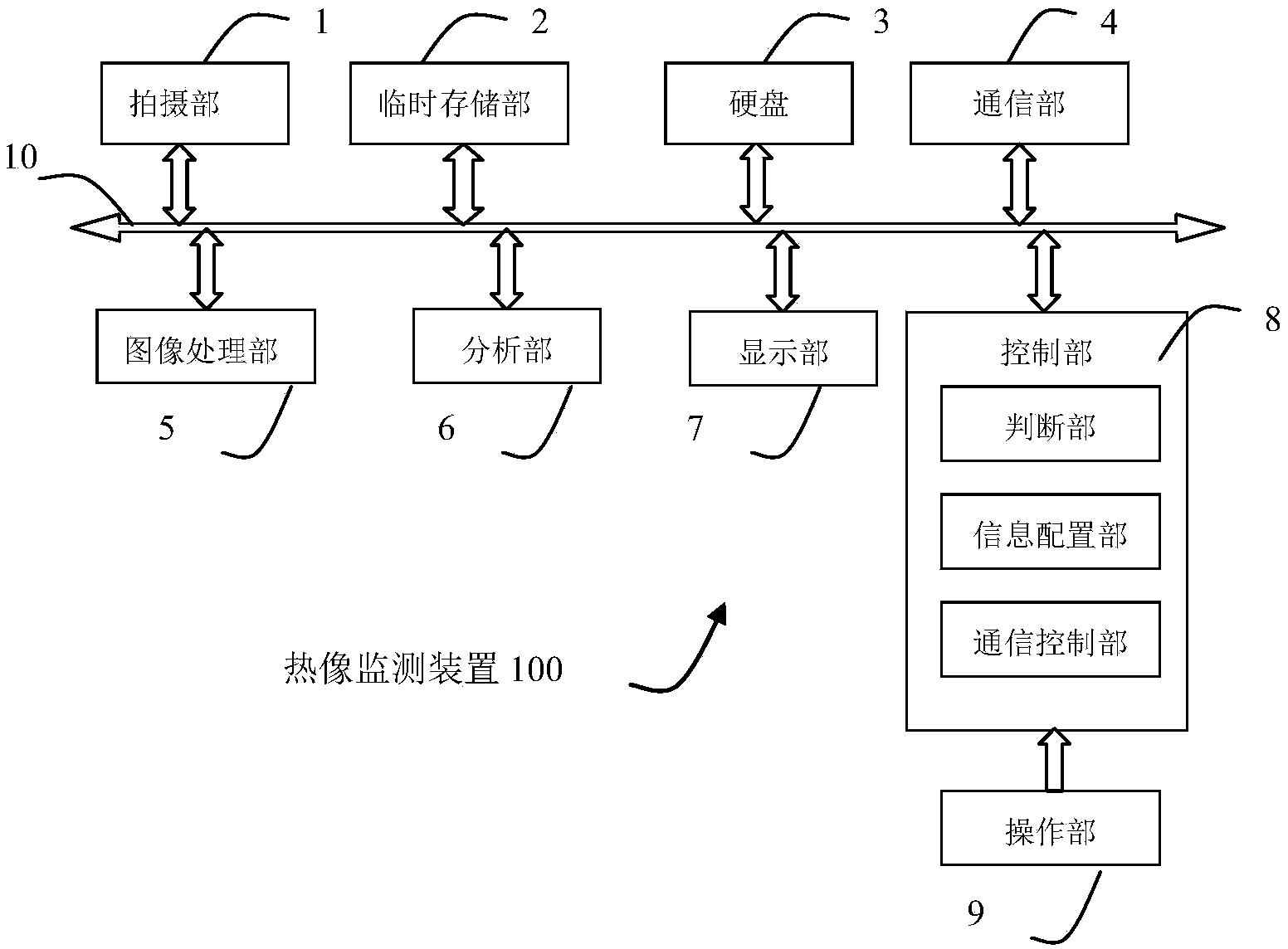
[0061] figure 1 It is a block diagram showing a schematic configuration of the thermal imaging device 100 according to Embodiment 1 of the present invention.

[0062] Specifically, the thermal imaging device 100 has a photographing unit 1, a temporary storage unit 2, a hard disk 3, a wireless communication unit 4, an image processing unit 5, an analysis unit 6, a display unit 7, a control unit 8, an operation unit 9, and a control unit 8. The overall control of the thermal ima...

Embodiment approach

[0073] The image processing part 5 is used to perform prescribed processing on the thermal image data frame obtained by the shooting part 1. The processing of the image processing part 5, such as correction, interpolation, pseudo-color, synthesis, compression, decompression, etc., is converted into a frame suitable for display. Processing of data for use, recording, etc. For example, when the display timing comes every time, from the thermal image data frames temporarily stored in the temporary storage unit 2 for a specified period of time, select and read out the frames at each specified time interval, and perform pseudo-color processing, Obtain the image data of infrared thermal images; an implementation of false color processing, for example, according to the range of thermal image data (in this embodiment, thermal image data refers to AD value) or the setting range of AD value according to the thermal image data frame To determine the corresponding pseudo-color table range...

Embodiment 2

[0146] The difference between Embodiment 2 and Embodiment 1 is that in this embodiment, there is an update unit (the control unit 8 has an update unit, which is omitted from the illustration) for updating the judgment conditions. When the judgment conditions are updated, the The judging unit is configured to judge whether the sending condition of the prescribed notification information is met according to the updated judging condition.

[0147] In Embodiment 1, when the object is greater than the specified fixed threshold, the specified notification information is sent to the user; when the subject is always greater than the specified fixed threshold, there may be excessive information notification to the user. In practical applications, after receiving the specified notification information, the user pays more attention to whether there is a trend of deterioration, but does not want to be disturbed too much.

[0148] In Embodiment 2, the control unit 8 further has an update u...


PUM


Abstract

A thermal image monitoring device and monitoring system, and a thermal image monitoring method of the present invention, relating to the application field of thermal image devices, thermal image processing apparatuses for receiving and processing thermal image data, and thermal image shooting. In the prior art, when data such as thermal image data frames are continuously transmitted to a background computer, a user needs to monitor thermal image data, etc. of a shot object for a long time, so that the user is apt to fatigue and then omits emergency situations. Provided are a thermal image monitoring device and monitoring system, and a thermal image monitoring method. Configured specified notification information is sent according to a sending condition of specified notification information, thereby achieving the beneficial effects of continuous monitoring, difficult omission of emergency situations, reduction of labour intensity, reduction of system costs, and simple use.

Description

technical field [0001] The thermal image monitoring device, monitoring system and thermal image monitoring method of the present invention relate to a thermal image monitoring device, a thermal image processing device for receiving and processing thermal image data frames, and the application field of thermal image shooting. Background technique [0002] There is such a technology that sets up a thermal image monitoring device for continuous monitoring of the subject, and transmits the collected thermal image data frames to the background computer for analysis, infrared thermal image display and other processing, which is convenient for users Monitoring is carried out in the background, which realizes the separation of man and machine, which can reduce the labor intensity of users and ensure the safety of users. The application number of the published patent document: 200920113208.9 is a mobile workstation of a thermal image monitoring device using such a technology. [0003...

Claims


Application Information

Patent Timeline
Patent Type & Authority Applications(China)
IPC IPC(8): H04N5/33H04N7/18G01J5/10
CPCA61B5/015G01J5/025G01J5/026G01J2005/0077G01J5/0806G01J5/48H04N23/23
Inventor 王浩
Learn More