Flow guiding shell of submerged pump

A diversion shell and submersible pump technology, applied in the direction of pumps, pump components, non-variable-capacity pumps, etc., can solve the problems of increased water resistance in the water flow channel, complex shape of the diversion shell, and reduced submersible pump efficiency, etc. Reliability, abundant raw materials, and the effect of improving water intake efficiency

Inactive Publication Date: 2014-11-19
HOMTON ENTERPRISES
View PDF5 Cites 0 Cited by
  • Summary
  • Abstract
  • Description
  • Claims
  • Application Information

AI Technical Summary

Problems solved by technology

The inner and outer walls of the diversion shell are mostly composite curved surfaces, usually made of cast iron. However, the shape of the diversion shell is relatively complicated, and the water-touching surface cannot be machined, so it is easy to cause rough surface, which increases the water resistance in the water flow channel. This in turn reduces the efficiency of the submersible pump

Method used


Image

  • Flow guiding shell of submerged pump
  • Flow guiding shell of submerged pump

Examples


Embodiment

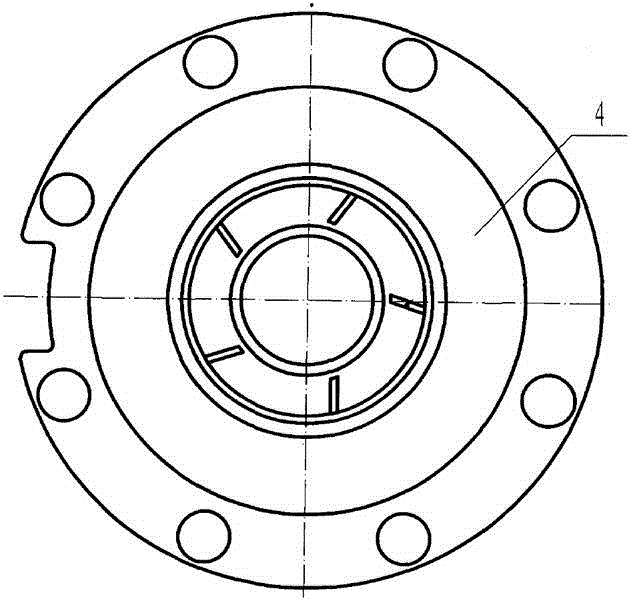
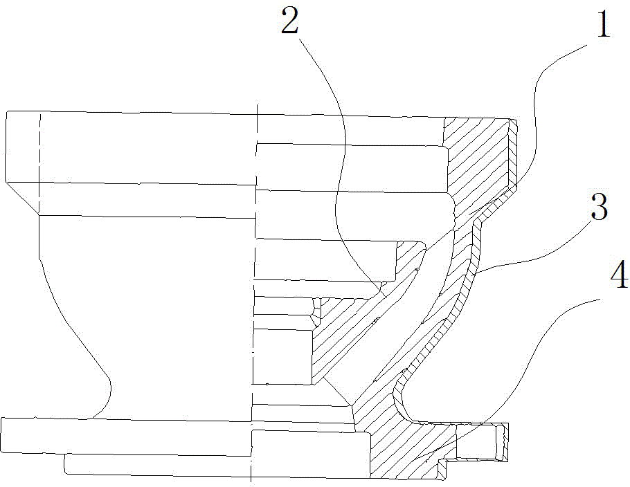
[0013] The diversion casing of the submersible pump in this embodiment is as follows: figure 1 and figure 2 As shown, it includes the shell 1 and the bearing frame 2. The upper part of the shell 1 is flange-shaped, and the lower part of the shell 1 is provided with a boss 4, and the bearing frame 2 is located below the inside of the shell 1; the shell 1 is made of ceramics, and the appearance of the shell 1 The bread is covered with a rubber layer3. The rubber layer 3 can be fixed on the surface of the casing 1 by wrapping a rubber strip around the surface of the casing 1, and the casing 1 and the rubber layer 3 are glued together with resin glue.

[0014] This embodiment utilizes the advantages that the ceramic surface of the shell 1 is smooth and easy to manufacture, and avoids the shortcomings of the rough surface of the guide shell made of cast iron, which is difficult to finish, thereby reducing the resistance of the water flow in the pipeline and improving the performa...


PUM


Abstract

The invention relates to a flow guiding shell of a submerged pump and belongs to the technical field of submerged pumps. The flow guiding shell of the submerged pump comprises an outer shell body and a bearing frame. The upper portion of the outer shell body is in a flange shape. A boss is arranged on the lower portion of the outer shell body. A locating groove located in the boss is formed in the lower portion of the interior of the outer shell body. The bearing frame is embedded into the locating groove. The outer shell body is made of ceramics. The outer surface of the outer shell body is wrapped in a rubber layer. By the adoption of the flow guiding shell, the water inflow efficiency of the submerged pump can be greatly improved.

Description

technical field [0001] The invention relates to a diversion shell of a submersible pump, which belongs to the technical field of submersible pumps. Background technique [0002] Existing submersible pumps are usually multi-stage vertical centrifugal pumps in which a motor and a water pump are combined. The water pump is composed of a centrifugal impeller and a diversion casing that is essentially a pump casing. When the submersible pump is in use, the impeller rotates at high speed, and the liquid in the submersible pump rotates with the blades. Under the action of centrifugal force, it flies away from the impeller and shoots outward. Slowly, the pressure gradually increases, and then flows out of the discharge pipe at the pump outlet. At this time, at the center of the blade, a vacuum low-pressure area without air and liquid is formed because the liquid is thrown to the surroundings. The liquid in the liquid pool flows into the submersible pump through the suction pipe und...

Claims


Application Information

Patent Timeline
Patent Type & Authority Applications(China)
IPC IPC(8): F04D29/44F04D29/02F04D29/04F04D29/66
Inventor 候潇寒张薇华陆俊芳张军
Owner HOMTON ENTERPRISES
Why Eureka
Try Eureka