
Center air ring concentrated type turbulent burner

A swirling burner and concentrated technology, which is applied in the direction of burners, burners for burning powder fuel, and combustion methods, can solve the problems of unfavorable pulverized coal preheating and volatilization analysis, increased carbon content of fly ash, and pulverized coal Delayed ignition and other issues, to achieve the effect of timely ignition and stable combustion, reduce the carbon content of fly ash, and reduce the carbon content of large slag

Inactive Publication Date: 2014-11-19
TRANSTEK IND HK LTD KOWLOON
View PDF6 Cites 4 Cited by
  • Summary
  • Abstract
  • Description
  • Claims
  • Application Information

AI Technical Summary

Problems solved by technology

[0004] The original concentrated swirl burner has certain deficiencies because the pulverized coal flow is in the center of the burner and surrounded by the rotating internal and external secondary air flow, which is mainly reflected in: 1) the pulverized coal is heated unevenly, It is beneficial to the preheating of pulverized coal and the precipitation of volatile matter; 2) The air distribution of pulverized coal is not good. Although the concentration of pulverized coal is high, the contact area between pulverized coal and air is small. rate is not high
These deficiencies will lead to the delay of ignition of pulverized coal and the reduction of combustion efficiency of pulverized coal, which will increase the carbon content of fly ash and large slag of the boiler. So, according to relevant experience, compared with when no SOFA is installed, the carbon content of the fly ash of the boiler will increase by 40-100%, which will reduce the economy of the boiler and increase the coal consumption of the power plant

Method used


Image

  • Center air ring concentrated type turbulent burner
  • Center air ring concentrated type turbulent burner
  • Center air ring concentrated type turbulent burner

Examples


Embodiment Construction

[0021] The novel "central wind ring concentration type swirl burner" provided by the present invention will be further described in detail below in conjunction with specific examples, but the present invention is not limited thereto.

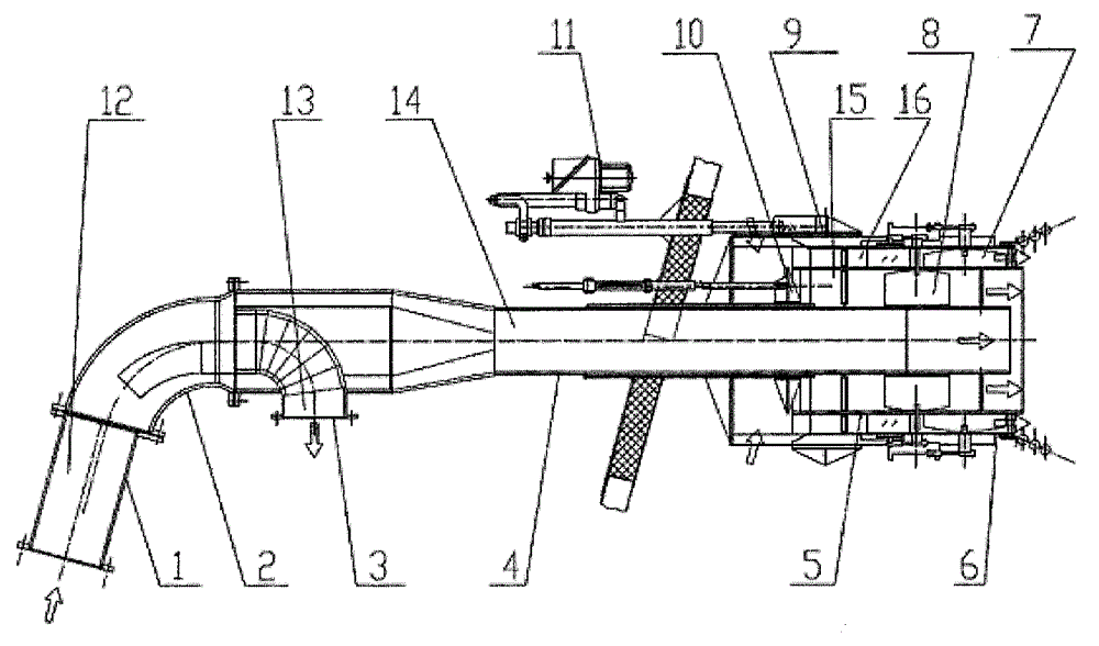
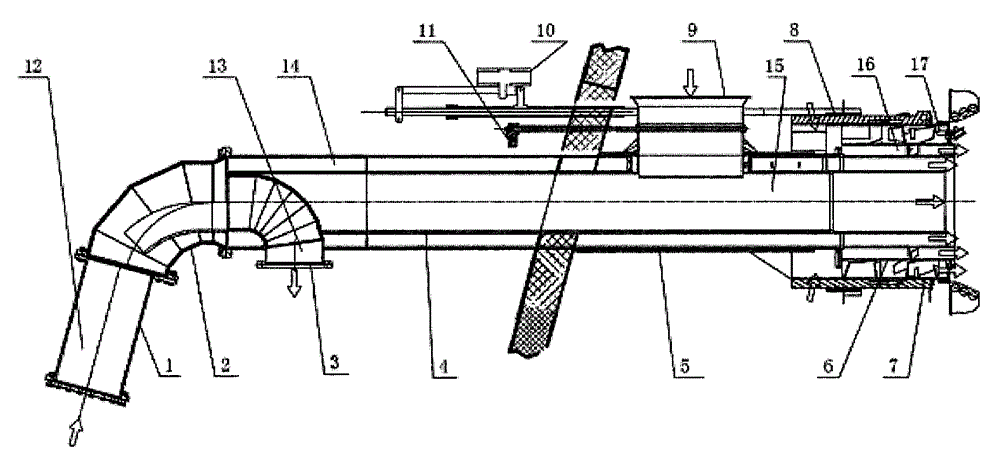
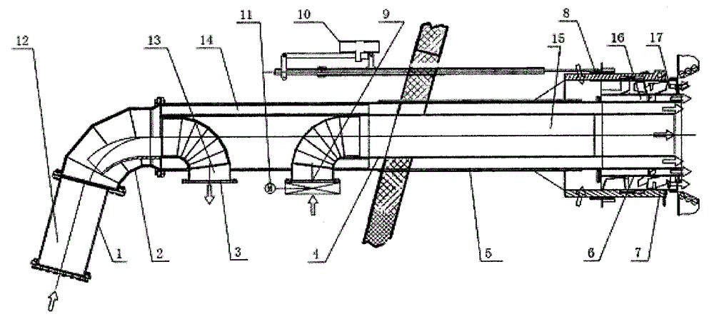
[0022] The central air ring concentrated swirl burner includes primary air pulverized coal pipeline, inner secondary air duct, outer secondary air duct, exhaust pipe, deflector duct, elbow, pulverized coal nozzle, and central air pulverized air in the pulverized primary air duct. Pipeline, the primary air pulverized coal pipeline and the central air pipeline form an annular passage, and the pulverized coal is heated by the high-temperature central air and internal secondary air in the annular passage.

[0023] Preferably, the pulverized coal nozzle is an annular nozzle, and after the pulverized coal is ejected from the annular nozzle, it is surrounded by the central air and the internal and external secondary air.

[0024] Preferably, the introd...


PUM


Abstract

A center air ring concentrated type turbulent burner comprises a primary air pulverized coal pipeline, an internal secondary air duct, an external secondary air duct, an exhaust gas pipe, a deflective guide pipe, an elbow and a pulverized coal nozzle. A center air pipeline is arranged in the primary air pulverized coal pipeline, the primary air pulverized coal pipeline and the center air pipeline form an annular channel, pulverized coal is heated by high-temperature center air and internal secondary air in the annular channel and can be heated more uniformly, and therefore more volatiles can be easily separated out, and timely ignition and steady burning of the pulverized coal can be easily achieved. The pulverized coal nozzle is of a circular ring shape, the pulverized coal is surrounded by the center air, the internal secondary air and the external secondary air after being ejected out from the circular-ring-shaped nozzle, two layers of flames are formed after the pulverized coal is ignited, burning of the pulverized coal is more violent and more efficient, and the fly ash carbon content and the cinder carbon content can be effectively decreased.

Description

technical field [0001] The invention relates to a novel central air ring concentrated swirl burner, which belongs to the technical field of boiler pulverized coal combustion. Background technique [0002] For lean coal and anthracite counter-combustion pulverized coal boilers, concentrated burners (or hot air powder delivery methods) are usually used to solve the problems of coal pulverized ignition and stable combustion. Type overfired air) to control the NOx (nitrogen oxides) emission concentration at the outlet of the boiler economizer. [0003] The air inlet channel of the concentrated swirl burner is mainly composed of the primary air pulverized coal pipeline, the inner and outer secondary air ducts and the exhaust pipe. The primary air enters the furnace from the primary air pulverized coal pipeline, and its main function is to transport pulverized coal and provide the oxygen required for the combustion of volatile components in the pulverized coal combustion process....

Claims


Application Information

Patent Timeline
Patent Type & Authority Applications(China)
IPC IPC(8): F23D1/02
Inventor 张庆
Owner TRANSTEK IND HK LTD KOWLOON
Learn More