
An endoscopic detection device for a furnace cellar

A detection device, an endoscopic technology, applied in the field of furnace cellar endoscopic detection devices, can solve problems such as poor performance stability and reliability, increase the cost of replacing motors, and affect equipment reliability, so as to simplify control configuration and reduce installation costs. Maintenance complexity, effect of improving cooling effect

Active Publication Date: 2016-03-23
杨卫中 +1
View PDF8 Cites 0 Cited by
  • Summary
  • Abstract
  • Description
  • Claims
  • Application Information

AI Technical Summary

Problems solved by technology

[0002] As introduced in the previous patent (Patent No.: 200820034190.9) of the traditional endoscopic detection device in the furnace pit, the rotation of the lens barrel mainly relies on the motor to drive the worm to rotate, and the worm drives the rotation of the turbine to drive the connection to the flange. The lens barrel rotates. The defects brought about by this rotating structure are: first, the vibration is relatively large, and the lens barrel shakes seriously during the rotation, which is prone to defects that cannot be accurately positioned; second, because the motor part is close to the furnace cellar The outer wall, so the motor is heated very seriously even when it is not working. If the working time is a little longer, the motor is very easy to burn out, which indirectly increases the cost of replacing the motor and affects the reliability of the equipment.
[0003] Omnidirectional video detection of furnace high temperature resistance is an important means of quality control of high temperature industrial thermal processing. Its reliability is the guarantee of product quality and safe operation of equipment. At the same time, it also determines social effects such as energy saving, environmental pollution, etc. The original "Kiln 3D Intelligent Video Detection System" has relatively poor thermal stability, especially the rotating motor and angle detection device. Due to the proximity to the inspection port, the ambient temperature is relatively high, the performance stability and reliability are also relatively poor, and frequent failures. The price of the original system configuration is high, and users are not satisfied

Method used


Image

  • An endoscopic detection device for a furnace cellar
  • An endoscopic detection device for a furnace cellar
  • An endoscopic detection device for a furnace cellar

Examples


Embodiment Construction

[0027] The present invention is described in further detail now in conjunction with accompanying drawing. These drawings are all simplified schematic diagrams, which only illustrate the basic structure of the present invention in a schematic manner, so they only show the configurations related to the present invention.

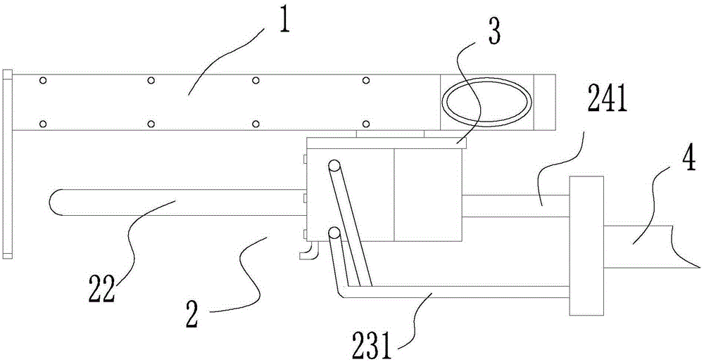
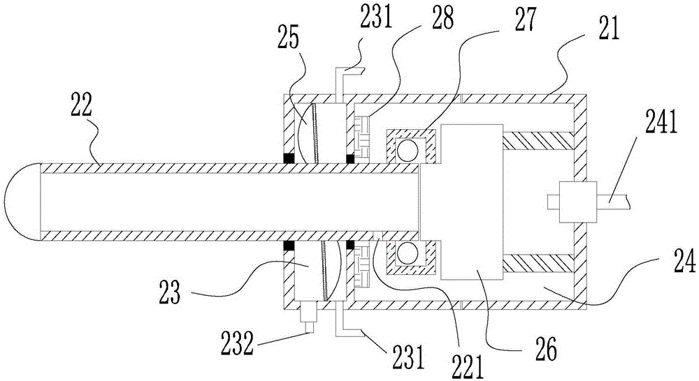
[0028] Such as figure 1 As shown, a furnace pit endoscopic detection device includes a mounting frame 1 and a fixed plate fixed on the front side of the mounting frame 1. The mounting frame 1 is provided with a forward and backward transmission mechanism. Patent No.: 200820034190.9) has been made public and will not be further elaborated here; a video detection device 2 is set under the installation frame 1, and the upper end of the video detection device 2 is connected with the sprocket of the forward and backward transmission mechanism through the installation plate 3, and the forward and backward transmission mechanism moves Drive the video detection devic...


PUM


Abstract

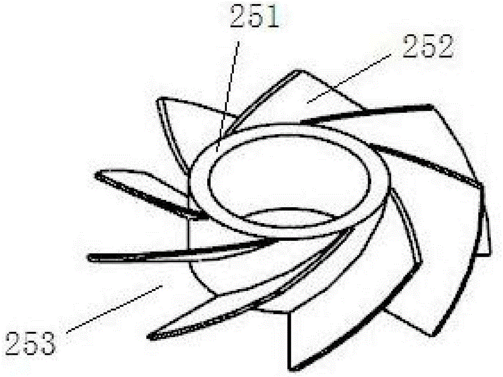
The invention relates to an intra-kiln detecting apparatus comprising a mounting rack and a video detector. A driving and reversing transmission mechanism is disposed on the mounting rack. The video detector is connected with the driving and reversing transmission mechanism through a sprocket. The video detector comprises a rear cylinder and a lens cylinder; a partition is disposed inside the rear cylinder and divides an inner cavity of the rear cylinder into a blade cavity and a camera cavity; the tail end of the lens cylinder penetrates the blade cavity and the partition; a first intake tube is connected to the rear end of the rear cylinder. A blade wheel is disposed on the lens cylinder inside the blade cavity. The outer wall of the rear cylinder is evenly and peripherally provided with a plurality of second air inlets around the blade wheel. The outer wall of the rear cylinder is further provided with air outlets around the blade wheel. High temperature resistance of the video detector is improved. Under the cooling action of the air outlets, the grade of a temperature field of the part, in contact with the wall of a kiln, of the video detector is greatly decreased, and the video detector is effectively protected from high temperature radiation.

Description

technical field [0001] The invention relates to an endoscopic detection device for a furnace pit. Background technique [0002] As introduced in the previous patent (Patent No.: 200820034190.9) of the traditional endoscopic detection device in the furnace pit, the rotation of the lens barrel mainly relies on the motor to drive the worm to rotate, and the worm drives the rotation of the turbine to drive the connection to the flange. The lens barrel rotates. The defects brought about by this rotating structure are: first, the vibration is relatively large, and the lens barrel shakes seriously during the rotation, which is prone to defects that cannot be accurately positioned; second, because the motor part is close to the furnace cellar The outer wall, so the motor is very heated even when it is not working. If the working time is a little longer, the motor is very easy to burn out, which indirectly increases the cost of replacing the motor and affects the reliability of the e...

Claims


Application Information

Patent Timeline
Patent Type & Authority Patents(China)
IPC IPC(8): F27D21/00
Inventor 杨卫中蔡舒旻盛希宁张晓燕
Owner 杨卫中
Learn More