
Spiral flat pipe type buried pipe

A technology of buried pipes and spirals, applied in the field of ground source heat pumps, can solve the problems of fluid flow not easily turbulent, low utilization rate of geothermal energy, limited contact surface, etc., to thin the flow boundary layer and reduce heat transfer heat The effect of resistance and flow velocity increase

Inactive Publication Date: 2014-11-19
TONGDU ENERGY TECH JIANGSU
View PDF14 Cites 1 Cited by
  • Summary
  • Abstract
  • Description
  • Claims
  • Application Information

AI Technical Summary

Problems solved by technology

[0004] The existing buried pipe heat exchange system of ground source heat pump uses PE pipe with smooth pipe wall, such as a corrugated elliptical heat exchange pipe disclosed in Chinese Patent No. 201320239557.1. The cross section of the heat exchange pipe body is elliptical. The longitudinal section is a continuous double-corrugated arrangement formed by connecting arc-shaped crests and two adjacent arc-shaped trough arcs by two connecting lines. Since there is no room in the heat exchange tube to increase the heat exchange surface and enhance turbulence structure, the fluid flow in it is not easy to achieve turbulent flow, and the contact surface between the fluid and the pipe body is limited, so the heat transfer effect is poor and the utilization rate of geothermal energy is low

Method used


Image

  • Spiral flat pipe type buried pipe
  • Spiral flat pipe type buried pipe
  • Spiral flat pipe type buried pipe

Examples


Embodiment 1

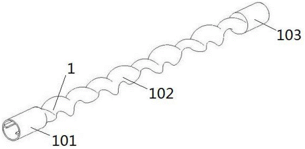
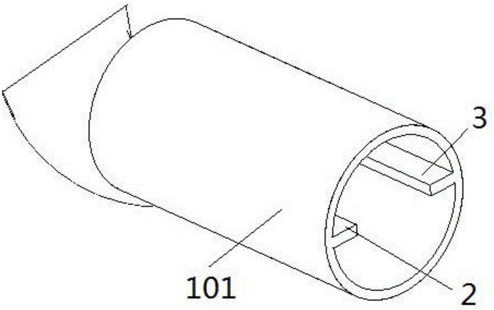
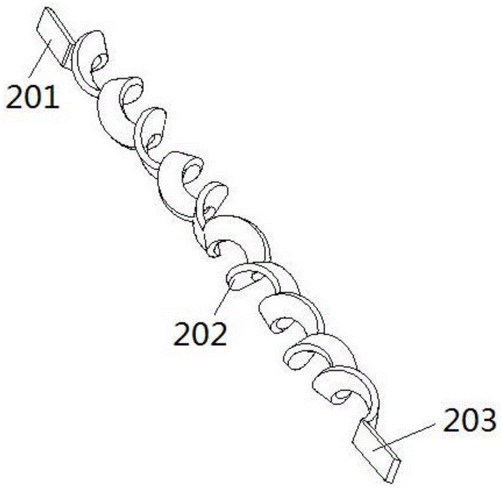
[0025] like figure 1 , figure 2 , image 3 As shown, a spiral flat pipe buried pipe includes a buried pipe body 1, the middle part of the buried pipe body 1 along the length direction is a curved pipe section 102, and one end of the buried pipe body 1 is an imported hot-melt The connecting pipe 101, the other end of the buried pipe body 1 is the outlet hot-melt connecting pipe 103, the inlet hot-melt connecting pipe 101, and the outlet hot-melt connecting pipe 103 are straight pipes with a circular cross section, and the curved pipe section 102 is a spiral rotation Shape, the spiral center line of the curved pipe section 102 coincides with the axes of the inlet hot-melt connecting pipe 101 and the outlet hot-melt connecting pipe 103, the cross-section of the curved pipe section 102 is elliptical, and the curved pipe section 102 is formed by winding a cylindrical helix in an elliptical ring; bending The enhanced heat transfer of the pipe section 102 is embodied in the follow...

Embodiment 2

[0029] With embodiment 1, the difference is, as Figure 4 , Figure 5 As shown, the number of heat exchange ribs is 3, and the cross section of the heat exchange ribs is trapezoidal. The heat exchange ribs 4 , the first heat exchange ribs 2 , the second heat exchange ribs 3 and the third heat exchange ribs 4 have the same structure. The trapezoidal cross-section design can further increase the contact area between the fluid and the pipe, which is more conducive to the heat transfer of the pipe. The number of heat exchange ribs is also increased to three, which can better enhance the turbulent flow.


PUM


Abstract

The invention discloses a spiral flat pipe type buried pipe and belongs to the technical field of ground source heat pumps. The spiral flat pipe type buried pipe comprises a buried pipe body. The two ends of the buried pipe body in the length direction are straight pipe sections, the middle of the buried pipe body is a bent pipe section which is of a spiral rotary shape, and the section of the bent pipe section is oval. Protruding heat exchange ribs are arranged in the buried pipe body and attached to the inner wall of the buried pipe body. According to the spiral flat pipe type buried pipe, the heat exchange ribs capable of improving the fluid turbulence effect are arranged in the pipe and meanwhile the contact area between the pipe and water flow is increased, so that the heat transfer area is increased and the heat transfer effect is further improved.

Description

technical field [0001] The invention belongs to the technical field of ground source heat pumps, and more specifically relates to a spiral flat tube buried pipe. Background technique [0002] "Heat pump" is a kind of work done by electricity, which captures low-grade heat energy from natural air, various water bodies, stratum structures or other media, transfers and upgrades it to high-grade heat energy that can be used by people for production and life. The heat pump consumes one Electric energy can provide 3-6 (even higher) high-grade heat energy, and its primary energy utilization rate exceeds 100%. [0003] The ground source heat pump system raises the temperature of the low-grade heat energy in the earth through the heat pump unit in winter to heat the building, and at the same time stores the cold energy of the building underground for summer use; in summer, the heat of the building is transferred through the heat pump into the ground, cooling the building while stori...

Claims


Application Information

Patent Timeline
IPC IPC(8): F28F1/08F28F1/40F25B30/06
CPCF24T10/10F28F1/08Y02E10/10
Inventor 王振宇刘东
Owner TONGDU ENERGY TECH JIANGSU
Learn More