Hall-effect large-diameter pipeline flowmeter

A large-caliber pipeline and Hall effect technology, which is applied in the direction of detecting fluid flow and volume/mass flow generated by electromagnetic effects with electromagnetic flowmeters, can solve the problems of inability to measure flow accurately, inconvenient installation and maintenance, and difficult manufacturing. Achieve good social and economic benefits, use less materials, and lower costs

Inactive Publication Date: 2014-11-19
衢州市鼎盛化工科技有限公司
View PDF12 Cites 6 Cited by
  • Summary
  • Abstract
  • Description
  • Claims
  • Application Information

AI Technical Summary

Problems solved by technology

As the diameter of the pipeline increases, the magnetic rotor increases accordingly, and the volume of the flow sensor also increases. At present, it has not been used in large pipelines. At the same t

Method used


Image

  • Hall-effect large-diameter pipeline flowmeter
  • Hall-effect large-diameter pipeline flowmeter
  • Hall-effect large-diameter pipeline flowmeter

Examples


Embodiment 1

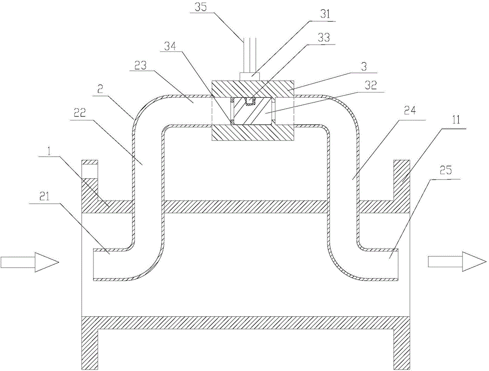
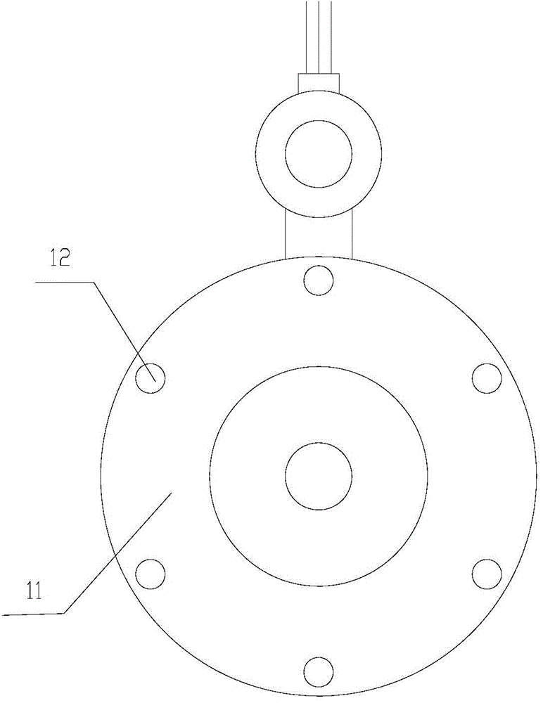
[0029] Such as figure 1 As shown, the two ends of the small-diameter branch pipe 2 are embedded in the large-diameter pipe 1, and the small-diameter pipe 2 includes a horizontal inlet port 21, an ascending section 22, a horizontal section 23, a descending section 24, and a horizontal outlet port 25; the horizontal inlet port 21, The horizontal section 23 and the horizontal outlet end 25 are parallel to the large-diameter pipe 1, and the ascending section 22 and the descending section 23 are perpendicular to the large-diameter pipe 1; The flow direction of the caliber tube 1 is the same; figure 2 As shown, the two ports of the large-diameter pipe 1 are provided with a connecting edge 11, and the connecting edge 11 is provided with a bolt hole 12, which can be connected with the pipe to be measured through a flange. figure 1The direction indicated by the middle arrow is the direction of fluid flow, which enters from the left end of the large-diameter pipe 1 and flows out from ...

Embodiment 2

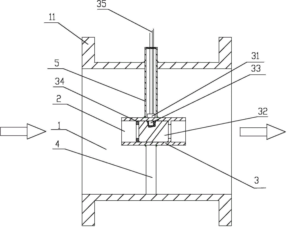
[0033] Such as image 3 As shown, the small-diameter branch pipe 2 is completely arranged in the large-diameter pipe 1, the bottom of the small-diameter branch pipe 2 is fixedly connected with the lower inner wall of the large-diameter pipe 1 through the lower support rod 4, and the top of the small-diameter branch pipe 2 is connected to one end of the upper branch pipe 5. Fixedly connected, the other end of the upper branch pipe 5 passes through the upper inner wall of the large-diameter pipe 1. The top connection between the upper branch pipe 5 and the small-diameter branch pipe 2, and the place where the upper branch pipe 5 passes through the outer wall of the large-diameter pipe 1 are all waterproofed and sealed. The two ports of the large-diameter pipe 1 are provided with connecting edges 11, and the connecting edges 11 are provided with bolt holes (the figure is shown, and can refer to figure 2 ), which can be connected with the pipe to be measured through the flange. ...


PUM


Abstract

The invention discloses a Hall-effect large-diameter pipeline flowmeter and a method thereof for measuring flow of large-diameter pipelines. The Hall-effect large-diameter pipeline flowmeter comprises a large-diameter pipe and a small-diameter branch pipe, two ends of the small-diameter branch pipe are arranged in the large-diameter pipe, and a Hall flow sensor is arranged in the small-diameter branch pipe. By means of the theory of Hall effect and the principle that flow value of the large-diameter pipe is proportional to that of the small-diameter branch pipe, numerical value of the large-diameter pipeline flowmeter is worked out by pulse signal frequency value of the flow sensor of the small-diameter branch pipe according to the formula Q=KF, and the K in the formula is accurately calibrated during manufacture of the flowmeter. Accordingly, the large-diameter pipeline flowmeter is convenient to manufacture, low in material consumption, low in cost, small and convenient to mount, use and maintain and brings considerable social and economic benefits.

Description

technical field [0001] The invention relates to a pipeline flowmeter, in particular to a flowmeter using Hall elements for large-diameter pipelines. Background technique [0002] In the industrial field, instruments that measure fluid flow are collectively referred to as flowmeters or flow meters. Flow meters are one of the major types of instruments in process automation instruments and devices. They are widely used in metallurgy, electric power, coal, chemical industry, petroleum, transportation, construction, textile, food, medicine, agriculture, environmental protection and people's daily life. It is an important tool for developing industrial and agricultural production, saving energy, improving product quality, improving economic efficiency and management level, and occupies an important position in the national economy. In process automation instruments and devices, flow meters have two major functions: as a detection instrument for a process automation control syste...

Claims


Application Information

Patent Timeline
IPC IPC(8): G01F1/58
Inventor 应悦姜战应盛荣
Owner 衢州市鼎盛化工科技有限公司
Why Eureka
Try Eureka