
Gas leakage monitoring device based on background schlieren technology, and gas leakage monitoring method based on background schlieren technology

A gas leakage and background technology, which is applied in the field of devices for gas leakage monitoring and leakage point search, can solve the problems of high labor cost, difficulty in accurately locating the leakage point, and difficulty in accurately locating the gas leakage position, and achieves the effect of simple structure.

Inactive Publication Date: 2014-11-19
HEFEI INSTITUTES OF PHYSICAL SCIENCE - CHINESE ACAD OF SCI
View PDF3 Cites 12 Cited by
  • Summary
  • Abstract
  • Description
  • Claims
  • Application Information

AI Technical Summary

Problems solved by technology

[0003] The earliest method is to judge whether there is leakage by applying soap bubbles on the outer surface of the test. This method is simple but the labor cost is high.
Later, it developed to use the pressure change inside the device to monitor gas leakage, which is better for static devices. If the pressure of the device itself is constantly changing, it will affect the accuracy of the system, and this method is difficult to accurately locate the gas leakage location
With the development of spectroscopic technology, a large number of leakage telemetry technologies using characteristic gas absorption spectra have appeared. Through the detection and inversion of gas concentration of target leakage gas spectrum in a specific range, it can be judged whether there is leakage. This method can realize long-distance and large-scale Remote measurement, but usually a set of devices can only target one kind of leaking gas, and it is difficult to pinpoint the leaking point
The laser backscatter imaging technology and infrared spectral imaging technology, which also use the characteristic gas absorption spectrum, can determine the location of the leak point by imaging, but the device is more complicated, and it is only for a single gas monitoring, and the leakage of the compressed air pipeline invalid
American scholars also tried to use schlieren technology to monitor gas leakage by using air disturbance caused by leaking gas in the early days. This method has no restrictions on the type of leaking gas and is easy to determine the leak point, but it is difficult to achieve due to the limitation of the field of view of traditional schlieren technology. Large field of view monitoring

Method used


Image

  • Gas leakage monitoring device based on background schlieren technology, and gas leakage monitoring method based on background schlieren technology
  • Gas leakage monitoring device based on background schlieren technology, and gas leakage monitoring method based on background schlieren technology
  • Gas leakage monitoring device based on background schlieren technology, and gas leakage monitoring method based on background schlieren technology

Examples


Embodiment Construction

[0024] The present invention will be further described below in conjunction with the accompanying drawings and embodiments.

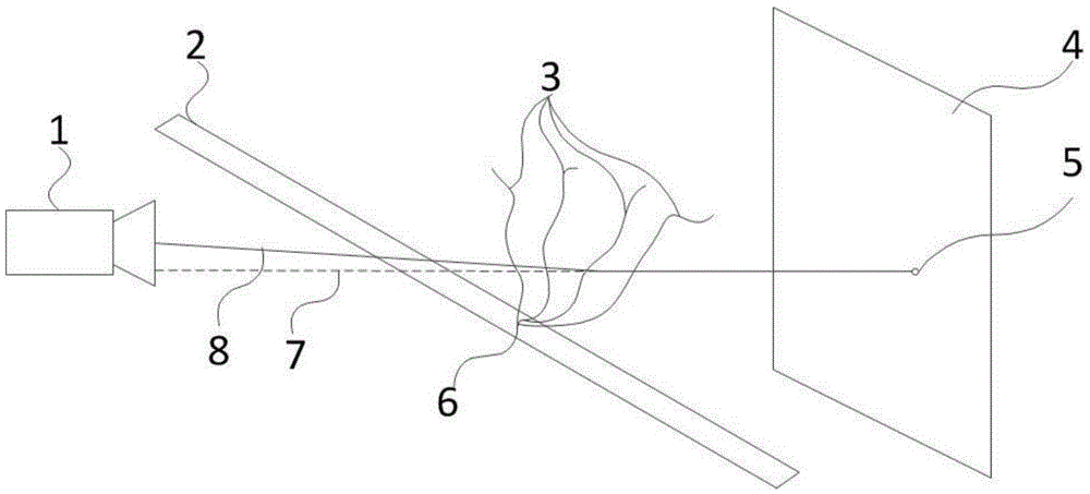
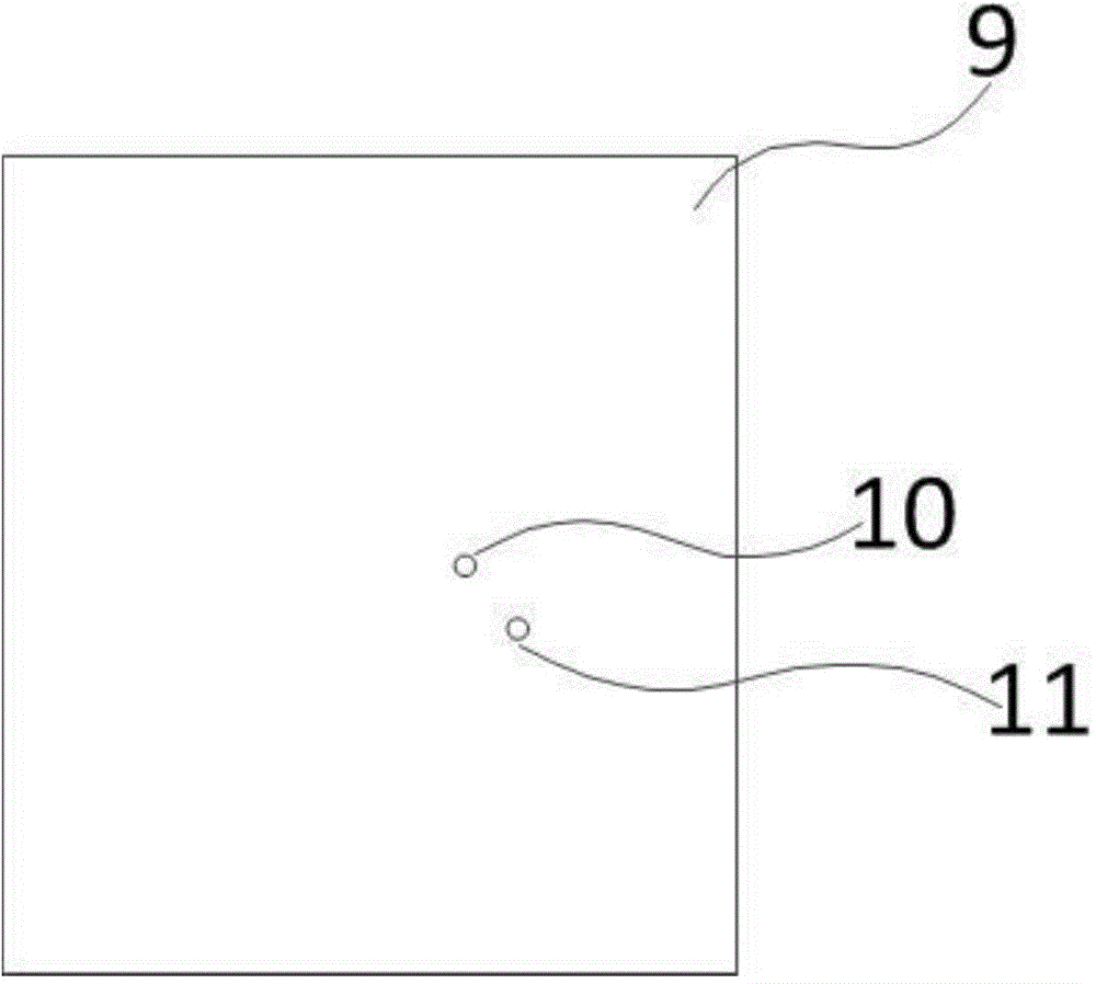
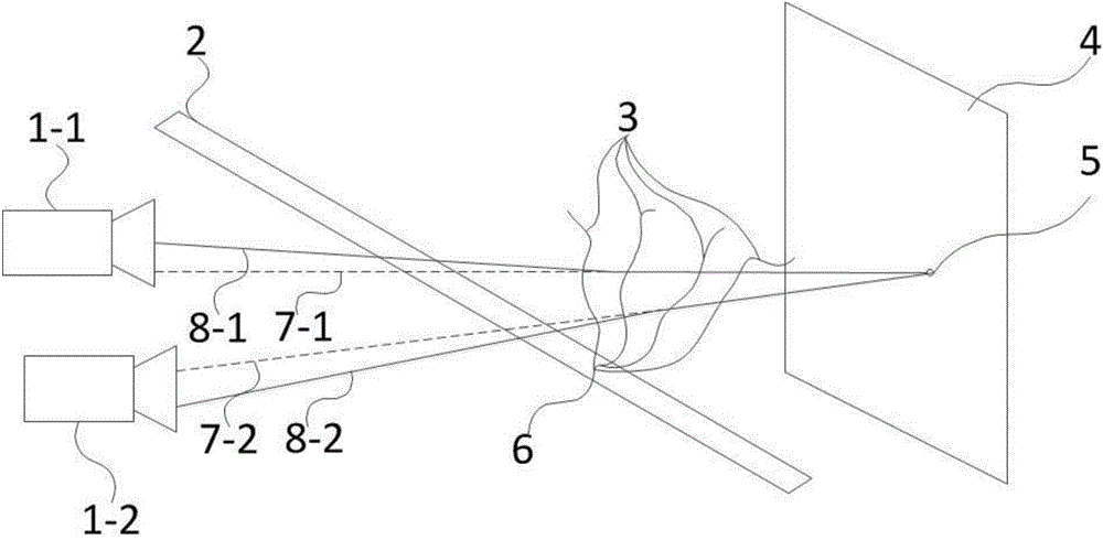
[0025] figure 1 Shown is one embodiment of the invention. The area array detector 1 collects photos of the background 4 behind the monitored device 2 in real time, and compares the latest two collected photos each time. If there is a gas leakage point 6 on the monitored object 2, the leaked gas will cause the air refractive index gradient change area 3 caused by the gas leakage. Take a certain point 5 on the background as an example, if the light emitted by 5 does not have the air refractive index gradient change area 3, it will be projected on the area array detector 1 along the direction 7, thereby imaging as the image point 11 of the background photo 9; but if The light emitted by the air refractive index gradient change regions 3 and 5 caused by gas leakage will be deflected and projected on the area array detector 1 along the direction 8, and ima...


PUM


Abstract

The present invention relates to a gas leakage monitoring device based on a background schlieren technology, and a gas leakage monitoring method based on the background schlieren technology. According to the present invention, based on the background schlieren technology, by comparing the two background photographs which are acquired at the different times or are acquired at the same time but at the different angles, and by the displacement of a lot of points on the photographs, the gradient change of an air refractive index in an area is detected, an air refractive index gradient change area caused by the gas leakage is identified, and the gas leakage is determined whether to occur, thereby determining the position of a leakage point. The device and method of the present invention are simple in structure, can monitor the gas leakage and search the leakage point in a large-range open environment and a complicated pipe network system, do not have selectivity to the gas types, and can monitor the all gas leakage.

Description

technical field [0001] The invention belongs to the field of gas leakage monitoring, and specifically relates to a device and method for realizing gas leakage monitoring and leakage point search by monitoring the turbulence caused by gas leakage to the surrounding air by using background schlieren technology. The invention is especially suitable for the monitoring of gas leakage in a wide range of open environments and the search for leakage points in complex pipe networks. Background technique [0002] Whether it is gas supply pipelines, gas storage devices or SF6 power equipment, there is a risk of gas leakage. Gas leakage will not only cause environmental pollution and waste of resources, but also seriously threaten the lives and property of the general public. Therefore, researchers have been looking for various gas leak monitoring methods. [0003] The earliest way to judge whether there is leakage is to apply soap bubbles on the outer surface of the test. This method ...

Claims


Application Information

Patent Timeline
IPC IPC(8): G01M3/38G01N21/45
Inventor 杨晨光刘建国阚瑞峰许振宇阮俊姚路王薇范雪丽戴云海
Owner HEFEI INSTITUTES OF PHYSICAL SCIENCE - CHINESE ACAD OF SCI
Learn More