Logical control device of droplet on micro-fluidic chip

A microfluidic chip and logic control technology, applied in the field of microfluidics, can solve the problems of chip temperature detection and heating, and achieve the effects of convenient operation, rapid mixing, and simple device structure

Active Publication Date: 2014-11-19
南京碟光生物科技有限公司
View PDF7 Cites 8 Cited by
  • Summary
  • Abstract
  • Description
  • Claims
  • Application Information

AI Technical Summary

Problems solved by technology

Since the traditional centrifugal force platform does not have a power supply system, the operations on the chip are mainly pass

Method used


Image

  • Logical control device of droplet on micro-fluidic chip
  • Logical control device of droplet on micro-fluidic chip
  • Logical control device of droplet on micro-fluidic chip

Examples


Embodiment Construction

[0035] Below in conjunction with accompanying drawing, technical scheme of the present invention is described in further detail:

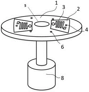
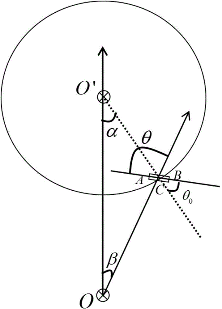
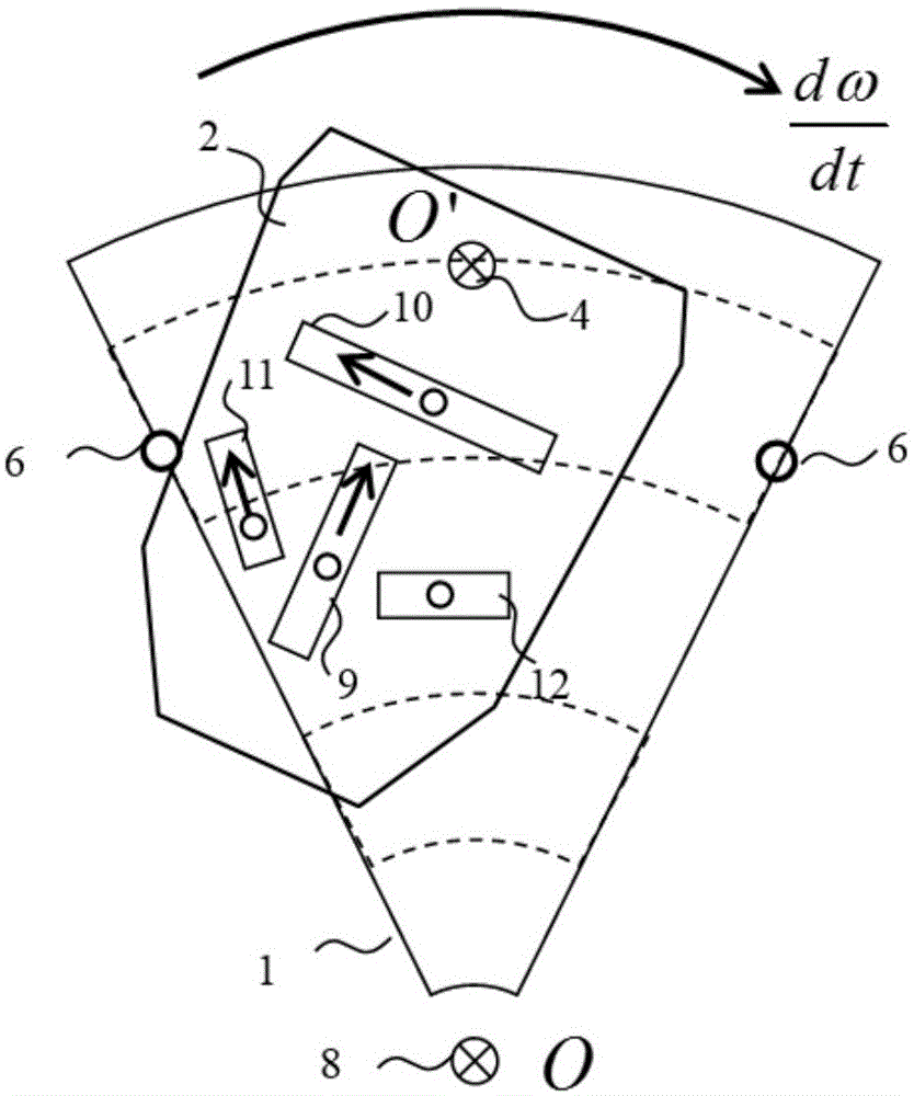
[0036] like figure 1 As shown, a droplet logic control device on a microfluidic chip includes a rotating platform with adjustable rotation speed, a microfluidic chip and at least one microfluidic pipeline, the microfluidic pipeline is an S-shaped pipeline or a Y-shaped pipeline, It also includes an auxiliary rotating shaft and two lock valves. The two locking valves are respectively arranged on both sides of the microfluidic chip. When the microfluidic chip rotates around the auxiliary rotating shaft, the microfluidic chip is locked in two positions by the locking valve. In terms of state, by controlling the rotational acceleration of the rotating platform and then adjusting the angle between the direction of the microfluidic pipeline and the radial direction of the rotating platform, the flow direction of the droplets in the microfluidic pipeline ...


PUM


Abstract

The invention discloses a logical control device of droplets on a micro-fluidic chip. The logical control device comprises a rotating platform with adjustable rotation speed, a micro-fluidic chip and at least one micro-flow pipes. The micro-flow pipes are S-shaped pipes or Y-shaped pipes. The logical control device also comprises auxiliary rotating shafts and two locking valves. The two locking valves are arranged at two sides of the micro-fluidic chip respectively. When the micro-fluidic chip rotates around the auxiliary rotating shafts, the micro-fluidic chip is locked on two states by the locking valves and adjusts included angles between micro-flow pipe directions and radial directions of the rotating platform through rotation acceleration of the rotating platform, so as to change droplet flow directions in the micro-flow pipes. The logical control device can control bi-directional flow of the droplets in the micro-flow pipes; and by introducing a binary logical control method, flow of the droplets in the micro-flow pipes can be controlled by using periodical timing sequence information, thereby mixing, reacting and detecting experimental samples more conveniently and quickly.

Description

technical field [0001] The invention relates to the field of microfluidic technology, in particular to a droplet logic control device on a microfluidic chip. Background technique [0002] Microfluidic chip technology is also known as "Lab on a Chip", that is, Lab On A Chip, which integrates the entire reaction and analysis process of biology, chemistry, and medicine into one chip, and automatically completes the entire process that was previously completed in the laboratory. The whole process of complex experiments. This includes basic operating procedures such as sample preparation, reaction, separation, and detection. Due to its great potential in the fields of biology, chemistry, and medicine, it has developed into a new research field interdisciplinary in biology, chemistry, medicine, fluid, electronics, materials, and machinery. [0003] Centrifugal force drive uses the centrifugal force generated when the chip moves in a circular motion driven by a micro-motor as the...

Claims


Application Information

Patent Timeline
IPC IPC(8): G01N35/00G05B19/042
Inventor 王光辉何浩培张旭苹应宙锋张益昕
Owner 南京碟光生物科技有限公司
Why Eureka
Try Eureka