Routing mechanism of winding machine

A winding machine and wire structure technology, which is applied in coil manufacturing, electromechanical devices, and motor generator manufacturing, can solve problems such as uneven tension control of enameled wires, inability to ensure consistent tension, and uneven shape of stator coils, etc., to achieve perfection Winding process, simple structure, smooth tension control effect

Inactive Publication Date: 2014-11-19
环一军
View PDF0 Cites 1 Cited by
  • Summary
  • Abstract
  • Description
  • Claims
  • Application Information

AI Technical Summary

Problems solved by technology

[0003] The wire routing mechanism of commonly used winding machines adopts the fishing rod type tension control structure, such as figure 1 As shown, the cage 5 is provided with a wire passing mechanism 3 and a fishing rod 2. After the enameled wire 1 is drawn out from the enameled wire reel 4, it passes through the wire mechanism 3 and the fishing rod 2 in turn and then enters the winding machine. The disadvantages of this structure are as follows: 1. The tension control of the enameled wire is uneven, and the fishing rod keeps beating in the process of controlling the tension, so the consistency of the tension cannot be guaranteed. There are loose and tight, and the shape of the stator coil wound out is uneven; 2. Due to the inconsistent tension of the fishing rod, the The enameled wire is easy to break, and the qualification rate of the stator coil is reduced; 3. The fishing rod keeps beating during the process of controlling the tension, which produces a lot of noise

Method used


Image

  • Routing mechanism of winding machine
  • Routing mechanism of winding machine

Examples


Embodiment Construction

[0010] The present invention will be further described below in conjunction with accompanying drawing, but not as limiting the present invention:

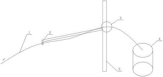
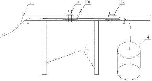
[0011] A wiring structure of a wire winding machine, comprising an enameled wire 1, a wire passing mechanism 3, and a cage 5, and the cage 5 is provided with a wire passing mechanism 3; after the enameled wire 1 is drawn out from the enameled wire reel 4, it passes through the wire mechanism 3 to enter the winding machine, the wire passing mechanism 3 is composed of several wool felts 301 arranged up and down, and each wool felt 301 is provided with an adjusting nut 302, and the enameled wire 1 passes through the wool felts 301 arranged up and down.

[0012] During specific implementation, after the enameled wire 1 is drawn from the enameled wire reel 4, the wool felt 301 of the wire mechanism 3 enters the winding machine, and the tension of the enameled wire 1 is controlled by the adjusting nut 302. The tightening force between the...


PUM


Abstract

The invention discloses a routing mechanism of a winding machine. A wire passing mechanism is arranged on a holding frame, an enamel covered wire is led out from an enamel covered wire plate, passes through the wire passing mechanism and enters the winding machine, the wire passing mechanism is composed of a plurality of pieces of wood felt which are arranged in an up-and-down mode, each piece of wool felt is provided with an adjusting nut, and the enamel covered wire penetrates through the wool felt which is arranged in the up-and-down mode. According to the routing mechanism of the winding machine, the structure is simple, faults are few, maintaining is convenient, noise pollution is reduced, stable tension control is provided, the winding process of products is improved, and production efficiency is improved.

Description

technical field [0001] The invention belongs to the technical field of motor manufacturing, and in particular relates to a wiring structure of a winding machine. Background technique [0002] Most electrical products need to be wound with enameled wires to make inductance coils, so winding machines are needed, such as: various motors, fluorescent lamp ballasts, transformers of various sizes, inductance coils for TVs and radios, line output transformers, electronic High-voltage coils on igniters and fire mosquitoes, speakers, earphones, voice coils of microphones, and various welding machines, the coils in these need to be wound by winding machines. [0003] The wire routing mechanism of commonly used winding machines adopts the fishing rod type tension control structure, such as figure 1 As shown, the cage 5 is provided with a wire passing mechanism 3 and a fishing rod 2. After the enameled wire 1 is drawn out from the enameled wire reel 4, it passes through the wire mechan...

Claims


Application Information

Patent Timeline
Patent Type & Authority Applications(China)
IPC IPC(8): H01F41/06H02K15/04H01F41/094H01F41/096
Inventor 环剑斌李洪淦董正刚展卫红陈银林张小媛李士新王虎
Owner 环一军
Why Eureka
Try Eureka