Gradient dry degumming method

A dry degumming and gradient technology, applied in optics, instruments, opto-mechanical equipment, etc., can solve problems such as affecting device performance, slowing down the heating rate, slow removal, etc., to improve product yield and avoid bursting.

Active Publication Date: 2017-09-29
SHANGHAI HUALI MICROELECTRONICS CORP
View PDF5 Cites 0 Cited by
  • Summary
  • Abstract
  • Description
  • Claims
  • Application Information

AI Technical Summary

Problems solved by technology

However, in order to prevent poping defects, the process slows down the heating rate by adjusting the distance between the wafer and the heating components, and reduces the reaction rate by reducing the oxygen content. Its main purpose is to slowly remove the hard shell on the surface of the photoresist and reduce defects, but Defect performance is still not ideal in the face of higher dose implant conditions
[0011] In step L03, use CF 4 Reactive gas can effectively remove photoresist (C-Si-O) residues and surface hard shell residues, but it will have other adverse effects on the device
due to CF 4 The gas has strong etching and corrosiveness, which will bring new etching damage to the oxide film or nitride film on the side wall of polysilicon, the silicon or oxide film substrate, and cause the critical dimension of the device or the amount of damage to the substrate silicon. change, which affects the performance of the device

Method used


Image

  • Gradient dry degumming method
  • Gradient dry degumming method
  • Gradient dry degumming method

Examples


Embodiment Construction

[0032] In order to make the content of the present invention clearer and easier to understand, the content of the present invention will be further described below with reference to the accompanying drawings. Of course, the present invention is not limited to this specific embodiment, and general substitutions known to those skilled in the art are also covered within the protection scope of the present invention.

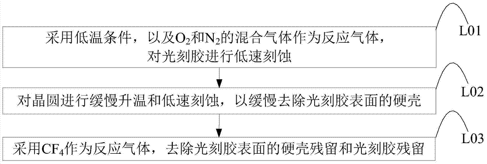
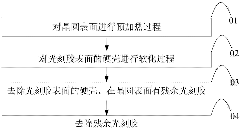
[0033] As mentioned above, the use of the existing plasma dry degumming process will cause process defects in the process of degumming, and the application of the degumming process is also limited; in this regard, the present invention provides a gradient dry The degumming method uses a gradient method to gradually remove the hard shell and photoresist; first, the preheating process can provide a certain starting temperature for subsequent reactions, and the preheating process can also ensure a slow reaction rate; secondly, The softening process, which splits the lo...


PUM


Abstract

The invention provides a gradient type dry photoresist removing method. A wafer with photoresist is employed, and the surface of the photoresist is provided with a hard shell which is formed through the injection of high energy particles. The method comprises a step of carrying out pre-heating on the surface of the wafer, a step of softening the hard shell at the surface of the photoresist, a step of removing the hard shell at the surface of the photoresist and leaving the residual photoresist at the surface of the wafer, and a step of removing the residual photoresist. By employing the method of the invention, the photoresist can be effectively removed, the process defects of photoresist burst, residue and polysilicon damage can be avoided, and the yield of products is improved further.

Description

technical field [0001] The invention relates to the technical field of semiconductors, in particular to a gradient dry method for degumming. Background technique [0002] In the front-end process of semiconductor wafer production, after photoresist coating, exposure, development and other processes of the wafer, after the high-energy particle implantation, the exposed pattern is the area that needs ion implantation according to the electrical characteristics of the product. A hard crust of a certain thickness is formed on the surface of the area covered by the photoresist. This hard shell is mainly composed of cross-linked carbon chain compounds and doped with various implanted ionic components. This brings more difficulties and challenges to the subsequent degumming process, which is often accompanied by process defects such as residue, popping, and even polybroken, which affects the yield of the product. to negative effects. [0003] In view of the above problems, the p...

Claims


Application Information

Patent Timeline
Patent Type & Authority Patents(China)
IPC IPC(8): H01L21/3105G03F7/42
CPCG03F7/427H01L21/31138
Inventor 荆泉高腾飞任昱吕煜坤朱骏张旭升
Owner SHANGHAI HUALI MICROELECTRONICS CORP
Why Eureka
Try Eureka