Method for controlling virtual reactance of photovoltaic grid-connected inverter

A control method and virtual reactance technology, applied in photovoltaic power generation, single-network parallel feeding arrangement, etc., can solve problems such as poor stability of photovoltaic grid-connected inverters, achieve enhanced system stability, increase output impedance, and improve output The effect of impedance

Inactive Publication Date: 2014-11-19
HARBIN INST OF TECH +1
View PDF4 Cites 17 Cited by
  • Summary
  • Abstract
  • Description
  • Claims
  • Application Information

AI Technical Summary

Problems solved by technology

[0004] In order to solve the problem of poor stability of existing photovoltaic grid-connected inverters, the present invention proposes a virtual reactance control method for photovoltaic grid-connected inverters

Method used


Image

  • Method for controlling virtual reactance of photovoltaic grid-connected inverter
  • Method for controlling virtual reactance of photovoltaic grid-connected inverter
  • Method for controlling virtual reactance of photovoltaic grid-connected inverter

Examples


specific Embodiment approach 1

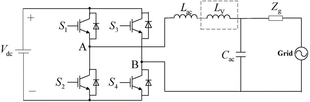
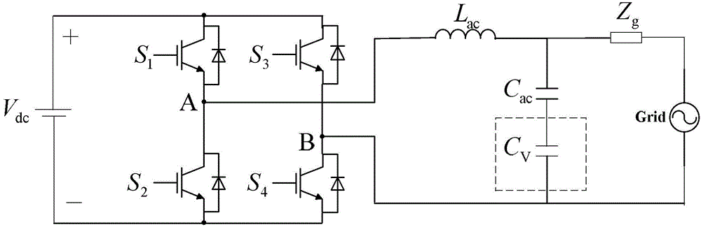
[0026] Specific implementation mode 1. Combination Figure 1-Figure 6 To illustrate this specific embodiment, the virtual reactance control method of a photovoltaic grid-connected inverter described in this specific embodiment includes the following steps:

[0027] Step 1. According to the actual grid impedance Z g , Photovoltaic grid-connected inverter output impedance Z o (s) and the amplitude-frequency characteristic and phase-frequency characteristic of the output impedance stability criterion of the photovoltaic grid-connected inverter to obtain the virtual inductance L V , The equivalent internal resistance r of the virtual inductance V and virtual capacitance C V ;

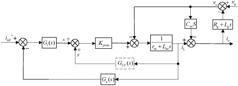
[0028] Step 2. According to the virtual inductance L V and the equivalent internal resistance r of the virtual inductance V , and combined with the full-bridge gain K PWM , to obtain the equivalent feedforward path transfer function G of the virtual inductor LV (s);

[0029] Step 3. According to th...

specific Embodiment approach 2

[0038] Embodiment 2. The difference between this embodiment and the virtual reactance control method of the photovoltaic grid-connected inverter described in Embodiment 1 is that the actual grid impedance Z described in step 1 g It is obtained through impedance testing equipment or grid impedance online detection method.

specific Embodiment approach 3

[0039] Specific embodiment 3. The difference between this specific embodiment and the virtual reactance control method of the photovoltaic grid-connected inverter described in the second specific embodiment is that the output impedance Z of the photovoltaic grid-connected inverter described in step 1 o The expression of (s) is:

[0040] Z o ( s ) = - v o i o | i L * = 0 ...


PUM


Abstract

The invention discloses a method for controlling the virtual reactance of a photovoltaic grid-connected inverter, and relates to the technical field of photovoltaic grid-connected inverter control. The problem that an existing photovoltaic grid-connected inverter is poor in stability is solved. The method includes the following steps: obtaining the virtual inductance value, the equivalent internal resistance of the virtual inductance value and the virtual capacitance according to the actual power grid resistance, the inverter output impedance and the inverter output impedance stability criterion; obtaining the equivalent feedforward passage transfer function of a virtual inductor in cooperation with full-bridge gains according to the virtual inductance value and the equivalent internal resistance of the virtual inductance value; obtaining the equivalent feedforward passage transfer function of a virtual capacitor in cooperation with the full-bridge gains, the actual filter capacitance, the filter inductor, the parasitic resistance of the filter inductor, the electric current loop transfer function and the feedback filter loop transfer function according to the virtual capacitance of the virtual capacitor; conducting discretization on the equivalent feedforward passage transfer functions of the virtual inductor and the virtual capacitor to obtain a difference equation; overlaying the difference equation and the electric current loop output value. The method is suitable for controlling the photovoltaic grid-connected inverter.

Description

technical field [0001] The invention relates to the technical field of photovoltaic grid-connected inverter control. Background technique [0002] The power grid at the end of the power grid in remote areas, islands, etc. is usually designed for relatively small loads, and its power supply is mostly of medium and low voltage levels. In order to meet the load needs of distributed users, most of the transmission lines are long and the line reactance is large, so the power grid presents high Impedance characteristics, this kind of grid is usually called weak grid (weak grid). For a photovoltaic grid-connected inverter with a reasonable design in the normal grid, when the grid impedance becomes larger, the stability of the system will deteriorate, and the harmonics of the grid-connected current will increase. Therefore, when designing photovoltaic inverters used at the end of the grid or in remote areas, not only the working state of the normal grid must be considered, but also...

Claims


Application Information

Patent Timeline
Patent Type & Authority Applications(China)
IPC IPC(8): H02J3/38
CPCY02E10/56
Inventor 王卫刘桂花刘鸿鹏曹小娇王盼宝吴辉
Owner HARBIN INST OF TECH
Why Eureka
Try Eureka