
Large-aperture static-state interference spectrum imaging instrument interferogram optical splicing method

A spectral imager and static interferometry technology, applied in the field of spectral imaging, can solve the problem that the size of the detector area array cannot meet the requirements of high spectral resolution, and achieve the effect of reducing the specification of the number of lines in the spectral dimension and improving the spectral resolution

Active Publication Date: 2014-11-26
XI'AN INST OF OPTICS & FINE MECHANICS - CHINESE ACAD OF SCI
View PDF5 Cites 5 Cited by
  • Summary
  • Abstract
  • Description
  • Claims
  • Application Information

AI Technical Summary

Problems solved by technology

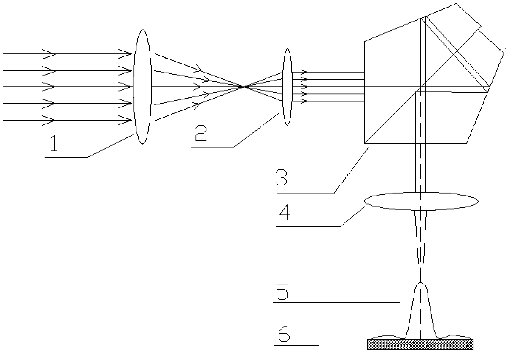
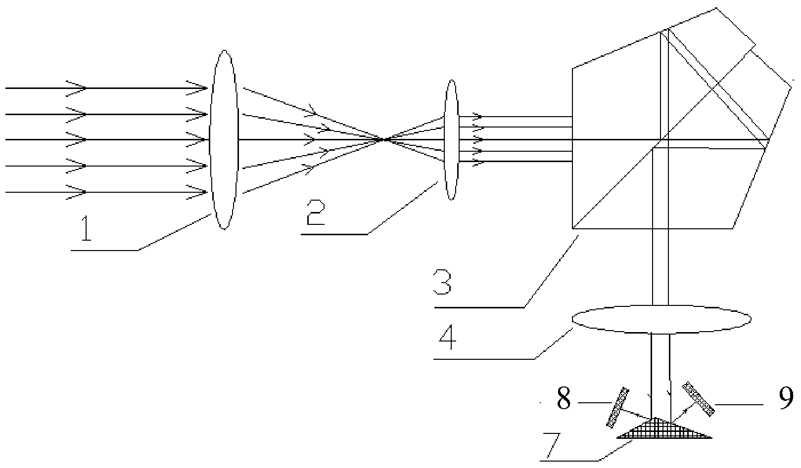
[0006] The purpose of the present invention is to provide a large-aperture static interference spectrum imager interferogram optical splicing method, which solves the technical problem that the detector area array specifications in the background technology cannot meet the high spectral resolution requirements

Method used


Image

  • Large-aperture static-state interference spectrum imaging instrument interferogram optical splicing method
  • Large-aperture static-state interference spectrum imaging instrument interferogram optical splicing method
  • Large-aperture static-state interference spectrum imaging instrument interferogram optical splicing method

Examples


specific Embodiment approach

[0038] The spectral resolution index of the large-aperture static interference spectral imager is 180 spectral bands, and the spectral range of the instrument is 0.45um~0.90um. Under the above indicators, the wave number resolution is 61.729cm -1 , the maximum optical path difference is 0.0081cm; according to the Nyquist sampling theorem, the sampling interval of the instrument is 2.25×10 -5 cm, so unilateral sampling requires 360 photodetector spectral lines; in order to ensure the accuracy of spectral data processing, interferogram zero-crossing sampling is required, and when the zero-crossing amount is 15%, it is 54 lines; at the same time, in order to avoid undersampling, Taking 15% oversampling corresponds to 54 lines of sampling points. Therefore, the instrument index requires that the number of photodetector spectral dimension lines be 468 lines during unilateral zero-crossing sampling.

[0039] When the maximum number of lines in the spectral dimension of the actual ...


PUM


Abstract

The invention relates to a large-aperture static-state interference spectrum imaging instrument interferogram optical splicing method. When a detector spectrum dimension row number cannot satisfy the requirement of a system design for an interferogram sampling point number, a reflector surface can be arranged before an image plane for segmenting the image plane in a spectrum direction, and interferograms are respectively sampled and converted by use of N detectors (N>=2); and during instrument push-scan imaging, the interferogram images of multiple detectors are ordered and spliced among multiple frames of data, and an interference image satisfying a data processing requirement is obtained. The method provided by the invention solves the technical problem of incapability of the array specification of a detector in satisfying a high-spectrum resolution requirement.

Description

technical field [0001] The invention relates to a spectral imaging technology, in particular to an interference spectral imaging technology. Background technique [0002] Spectral imaging technology combines spectral technology and imaging technology, and simultaneously obtains the geometric characteristics and radiation characteristics of the target to realize the comprehensive detection and identification of target characteristics. With the continuous improvement of space remote sensing applications for fine identification of target characteristics, the spectral resolution and spatial resolution indicators of spectral imaging instruments have been continuously improved. [0003] The spectral imaging technology applied to space remote sensing mainly has two technical principles: dispersion type and interference type. Interferometric spectral imaging technology has the characteristics of high sensitivity, high spectral resolution and high throughput, and can meet the requir...

Claims


Application Information

Patent Timeline
Patent Type & Authority Applications(China)
IPC IPC(8): G01J3/45
Inventor 刘强李思远陈小来王爽李芸李然
Owner XI'AN INST OF OPTICS & FINE MECHANICS - CHINESE ACAD OF SCI
Learn More