Inductance coil pin bending machine

An inductive coil and bending machine technology, applied in the field of pin bending devices, can solve the problems of high damage rate of inductive coil, short circuit of circuit board, lower product qualification rate, etc., so as to reduce labor intensity, improve bending accuracy, improve The effect of production efficiency

Active Publication Date: 2014-12-03
资兴市弘电电子科技有限公司
View PDF7 Cites 15 Cited by
  • Summary
  • Abstract
  • Description
  • Claims
  • Application Information

AI Technical Summary

Problems solved by technology

As the number of labor increases, the workers become more fatigued and the work efficiency decreases; in addition, the bending length and angle are controlled by the operators themselves, which will result in inconsistent product quality, high damage rate of the inductance coil, and reduce the qualified rate of the product
For example, the bends of the two legs are inconsistent and flat, and cannot be bonded to the surface of the printed circuit board. Too much bending will cause a local short circuit on the circuit board after welding, and too little bending will cause virtual soldering.
[0003] In the prior art, there is also a mechanized inductance coil pin bending device, including an inductance coil positioning mold, a limit pressing block, an upper bending punch, a foot cutting punch and a side bending punch; Every time the bending device bends an inductance coil, it needs to be manually removed from the positioning mold to pick up the parts, and the work efficiency is still not high.
Improper force to remove the mold and pick up the parts may cause the inductance coil to be bent, deformed and scrapped, and the pass rate of the product is still low
[0004] There is also a similar technical solution. On June 05, 2013, the Chinese utility model authorization announcement number CN 202963310 U disclosed a bending device for inductive wire pins, including a start button 1, a bending socket, an indicator light, and a start button 2. , protective cover, circuit board positioning hole, circuit board placement jig, electric control system, biaxial push cylinder 1, inductive wire straightening cylinder, biaxial push cylinder 2, inclined slider and pressure wheel, said circuit board placement jig There is an inductance wire straightening cylinder on the top. Although this device can realize the bending of the inductance wire pins, the inductance wire pins are inserted into the circuit board for bending. After each bending, the position of the circuit board needs to be adjusted. Reasons and other issues, its size is difficult to ensure consistency, and the yield rate is also low

Method used


Image

  • Inductance coil pin bending machine
  • Inductance coil pin bending machine
  • Inductance coil pin bending machine

Examples


Embodiment Construction

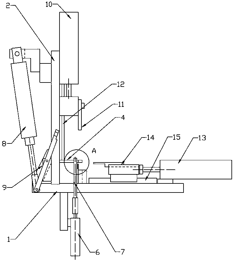
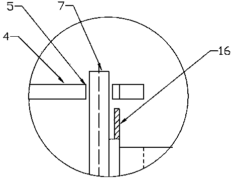
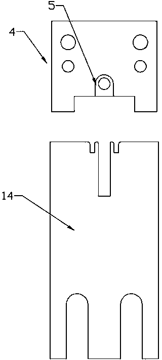
[0017] The present invention is described in further detail now in conjunction with accompanying drawing. The accompanying drawings are simplified schematic diagrams, which only illustrate the basic structure of the present invention in a schematic manner, so that they only show the components relevant to the present invention.

[0018] see figure 1 , figure 2 and image 3 ; An inductance coil pin bending machine, including a machine base 1, a machine base column 2, an inductance coil fixing block 4, an upper pressing assembly, a lower bending assembly, a side bending assembly and a control system; the inductance coil fixing block 4 is located at On the support in the middle of the frame column 2; the middle of the inductance coil fixing block 4 has a through hole 5, and there is a central positioning mandrel 7 driven by the first cylinder 6 directly below the through hole 5; when the piston rod of the first cylinder is in the extended state , the center positioning mandre...


PUM


Abstract

The invention relates to an inductance coil pin bending machine. The inductance coil pin bending machine comprises a machine base (1), a machine base stand column (2), an inductance coil fixing block (4), an upper pressing module, a lower bending module, a side bending module and a control system. The inductance coil fixing block (4) is arranged on a support in the middle of the machine base support column (2); the middle of the inductance coil fixing block (4) is provided with a through hole (5); a central positioning mandril (7) driven by a first air cylinder (6) is arranged right under the through hole (5). The inductance coil pin bending machine can rapidly bend the pins of an inductance coil, reduces the labor intensity of workers, improves the bending precision, reduces damage of the inductance coil, improves the utilization rate of the inductance coil and further improves the productivity.

Description

technical field [0001] The invention relates to a pin bending device of electronic components, in particular to an induction coil pin bending machine. Background technique [0002] With the development of electronic technology, SMT surface mount or surface mount technology has been widely used. In order to mount non-pin or short-lead surface mount components on the surface of printed circuit boards or other substrates, surface mount components are required. For example, inductance coils need to bend their pins before welding. In the prior art, in most cases, workers use small needle-nose pliers to manually bend. To complete the pre-soldering pin bending of 2000 circuit boards. As the number of labors increases, workers become more fatigued and work efficiency decreases; in addition, the bending length and angle are controlled by the operators themselves, which will result in inconsistent product quality, high damage rate of inductance coils, and lower product qualification ...

Claims


Application Information

Patent Timeline
Patent Type & Authority Applications(China)
IPC IPC(8): B21F1/00
Inventor 刘杰华谢武强
Owner 资兴市弘电电子科技有限公司
Why Eureka
Try Eureka