Inelastic collision and rolling viscous resistance particle coupling energy consumption numerical control machine tool

An inelastic collision, CNC machine tool technology, applied in maintenance and safety parts, metal processing mechanical parts, large fixed members, etc., can solve the problem of increasing the use of metal materials and manufacturing costs, reducing the stability of the machine bed, affecting the processing of workpieces Accuracy and other issues, to achieve the effect of obvious vibration suppression, small changes to the original structure, improved stability and machining accuracy

Active Publication Date: 2014-12-03
厦门环寂高科有限公司
View PDF6 Cites 2 Cited by
  • Summary
  • Abstract
  • Description
  • Claims
  • Application Information

AI Technical Summary

Problems solved by technology

[0002] At present, the development trend of CNC machine tools is high speed, high precision and high efficiency. However, high speed and heavy cutting will cause the stability of the machine bed to decline and affect the machining accuracy of the workpiece.
[0003] The common method used abroad to improve the stability of machine tools (H wang C, Jack C H, Wu T S, et al. Framework for integrated mechanical design automation [J]. Computer Aided Design, 2000; 32 (5): 355-365) is Carry out static and dynamic calculations for each component of the machine tool by finite element methods, a

Method used


Image

  • Inelastic collision and rolling viscous resistance particle coupling energy consumption numerical control machine tool
  • Inelastic collision and rolling viscous resistance particle coupling energy consumption numerical control machine tool
  • Inelastic collision and rolling viscous resistance particle coupling energy consumption numerical control machine tool

Examples


Embodiment Construction

[0029] The following embodiments will further illustrate the present invention in conjunction with the accompanying drawings.

[0030] see Figure 1-8 , the embodiment of the present invention is provided with CNC machine tool bed 11, CNC machine tool column 12, CNC machine tool beam 13, CNC machine tool top beam 14, CNC machine tool reinforcement beam 15, CNC machine tool ram 16, CNC machine tool electric spindle 17, CNC machine tool work Station 18;

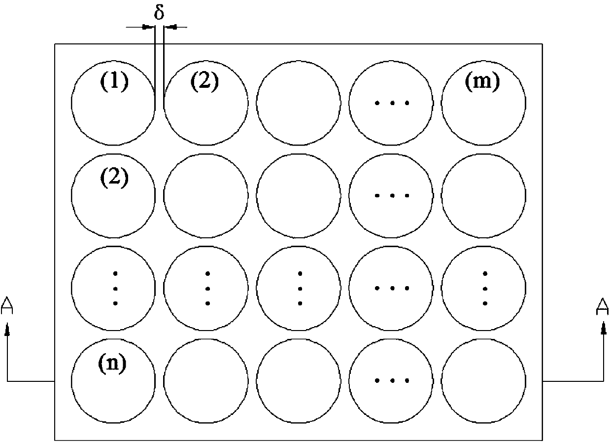
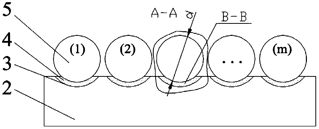
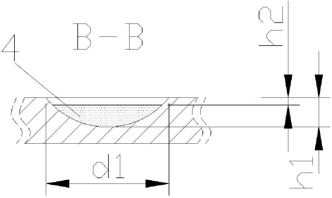
[0031] In the CNC machine bed 11, the CNC machine column 12, the CNC machine beam 13, the CNC machine top beam 14, the CNC machine reinforcement beam 15, and the CNC machine ram 16, at least two layers of coupling energy-dissipating plates 2 are respectively arranged. The energy plate 2 is provided with a groove array, in each groove of the groove array, at least 2 grains of high surface viscous resistance polymer particles 4 are placed, and in each groove 3, 1 grain of surface low coefficient of restitution grain 5 is placed ...


PUM

PropertyMeasurementUnit
Particle sizeaaaaaaaaaa
Densityaaaaaaaaaa
Particle sizeaaaaaaaaaa

Abstract

An inelastic collision and rolling viscous resistance particle coupling energy consumption numerical control machine tool relates to a numerical control machine tool and is provided with a numerical control machine tool body, upright posts, a crossbeam, a top beam, a stiffening beam, a ram, an electric spindle and a worktable, wherein at least two coupling energy consumption boards are arranged in at least one structural part of the numerical control machine tool, and the structural part comprises at least one of the numerical control machine tool body, the upright posts, the crossbeam, the top beam, the stiffening beam, the ram and the like; a groove array is arranged on each of the coupling energy consumption boards; at least two high-surface-viscous-resistance polymer particles are arranged in each groove of the groove arrays; a low-surface-recovery-coefficient particle is placed in each of the grooves. When the machine tool is in high-speed heavy cutting, the coupling energy consumption boards can quickly dissipate unidirectional and multi-directional vibration energy generated by the cutting force step by step, the energy consumption factor is high, the vibration suppression effect is obvious, and the stability and the machining precision of the machine tool are effectively improved.

Description

technical field [0001] The invention relates to a numerically controlled machine tool, in particular to an energy-consuming numerically controlled machine tool coupled with inelastic collision and rolling viscous resistance particles. Background technique [0002] At present, the development trend of CNC machine tools is high speed, high precision and high efficiency. However, high speed and heavy cutting will cause the stability of the machine bed to decrease and affect the machining accuracy of the workpiece. [0003] The common method used abroad to improve the stability of machine tools (H wang C, Jack C H, Wu T S, et al. Framework for integrated mechanical design automation [J]. Computer Aided Design, 2000; 32 (5): 355-365) is Static and dynamic calculations are carried out on each component of the machine tool by finite element methods, and the arrangement of ribs and structural support of each structural part of the machine tool is optimized. However, the disadvantage...

Claims


Application Information

Patent Timeline
IPC IPC(8): B23Q11/00B23Q1/01B23Q1/25
CPCB23Q11/0039
Inventor 肖望强
Owner 厦门环寂高科有限公司
Why Eureka
Try Eureka