

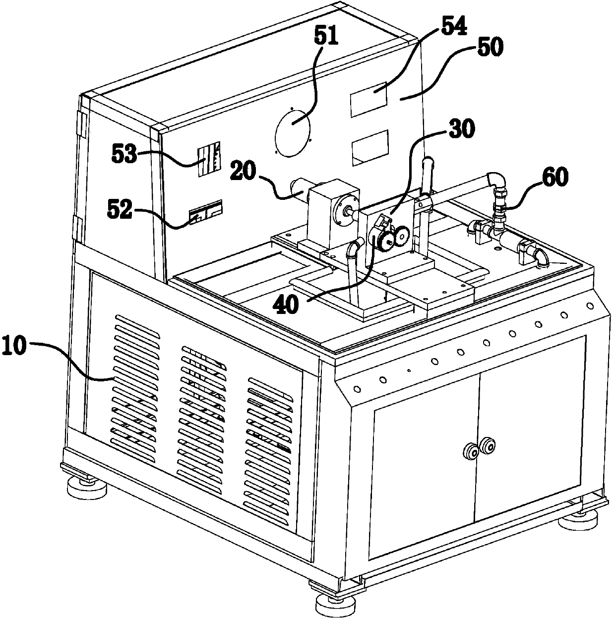
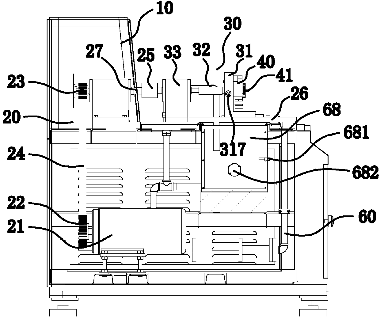
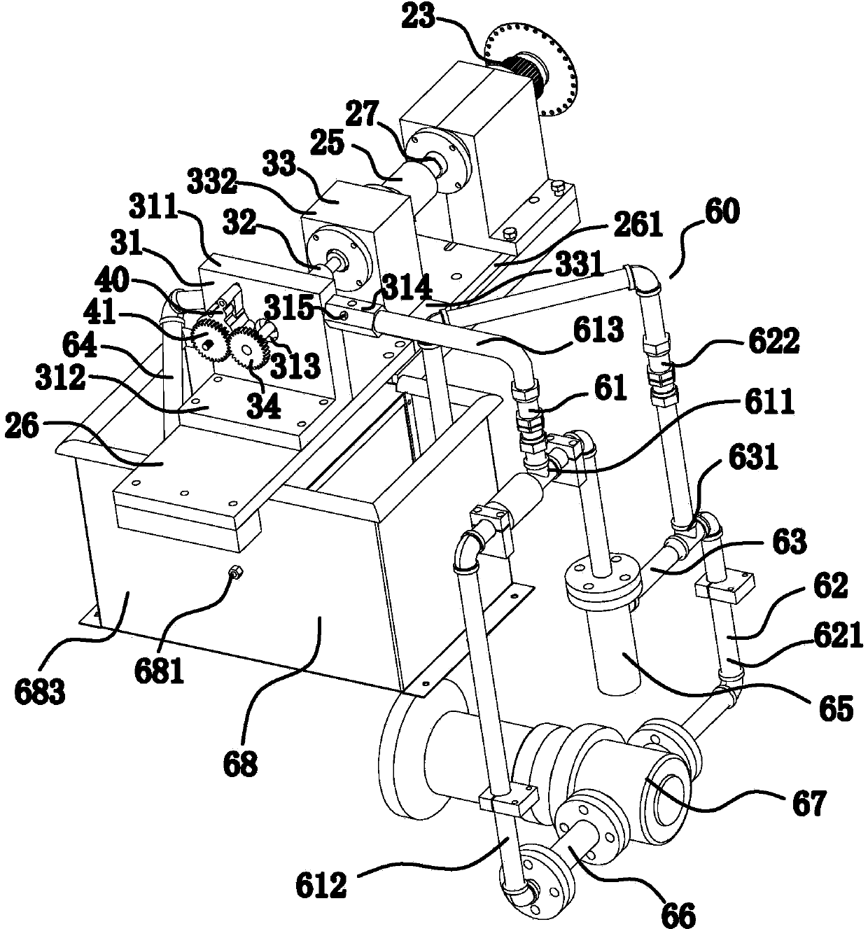
Horizontal test equipment for oil pump
A technology for testing equipment and oil pumps, applied in pump testing, mechanical equipment, heat treatment equipment, etc., can solve problems such as inaccurate test performance and inability to effectively reflect the working conditions of oil pumps, achieve good strength, improve service life, and save production cost effect
- Summary
- Abstract
- Description
- Claims
- Application Information
AI Technical Summary
Problems solved by technology
Method used
Image

Examples
Embodiment 1
[0069] According to the composition and mass percentage of the transmission shaft carbon quenched and tempered steel described in Table 1, Example 1, the raw materials are prepared, the raw materials are crushed and refined into metal powder, and the powder of small particles is made into large particles under hydrogen or vacuum conditions. or pellets;
[0070] Press the above-prepared large particle or aggregate powder into a transmission shaft blank under a pressure of 450 MPa, and sinter at 1050°C for 2 hours;
[0071] Carry out rough turning and semi-finish turning on the above-mentioned sintered drive shaft blanks, and then heat treatment, tempering at 680°C for 2 hours, normalizing at 860°C for 4 hours, and air cooling to 830°C for 2 hours after taking out of the furnace , and then cooled in water to 580°C and then oil-cooled to room temperature; tempered at 580°C for 2 hours, and air-cooled to obtain the transmission shaft in the horizontal test equipment of the oil pum...
Embodiment 2
[0073] According to the composition and mass percentage of the transmission shaft carbon quenched and tempered steel described in Table 1, Example 2, the raw materials are prepared, the raw materials are crushed and refined into metal powder, and the powder of small particles is made into large particles under hydrogen or vacuum conditions. or pellets;
[0074] Press the above-prepared large particle or aggregate powder into a transmission shaft blank under a pressure of 470MPa, and sinter at 1060°C for 2 hours;
[0075] Carry out rough turning and semi-finish turning on the above-mentioned sintered drive shaft blanks respectively, then heat treatment, temper at 690°C for 2 hours, normalize at 860°C for 4 hours, and air cool to 830°C for 2 hours after taking out the furnace , and then cooled in water to 590°C and then oil-cooled to room temperature; tempered at 590°C for 2 hours, and air-cooled to obtain the transmission shaft in the horizontal test equipment of the oil pump. ...
Embodiment 3
[0077] According to the composition and mass percentage of the transmission shaft carbon quenched and tempered steel described in Table 1, Example 3, the raw materials are prepared, the raw materials are crushed and refined into metal powder, and the powder of small particles is made into large particles under hydrogen or vacuum conditions. or pellets;
[0078] Press the above-prepared large particle or aggregate powder into a transmission shaft blank under a pressure of 490 MPa, and sinter at 1080° C. for 3 hours;
[0079] The above-mentioned sintered drive shaft blanks are subjected to rough turning and semi-finish turning respectively, and then heat treatment, tempering at 710°C for 3 hours, normalizing at 870°C for 5 hours, and air cooling to 850°C for 3 hours after being out of the furnace , and then cooled in water to 610°C and then oil-cooled to room temperature; tempered at 620°C for 4 hours, and air-cooled to obtain the transmission shaft in the horizontal test equipm...
PUM
 Abstract
Description
Claims
Application Information