Composite material plate structure damage monitoring method

A technology for composite material plate and damage monitoring, which is applied in the processing of detection response signals and the use of sound waves/ultrasonic waves/infrasonic waves to analyze solids, etc. It can solve the problem that the arrival time of scattered wave packets cannot be extracted, the efficiency of damage monitoring is reduced, and damage scattering cannot be accurately extracted Wave packet arrival time and other issues, to achieve high accuracy, save time, and eliminate interference

Active Publication Date: 2014-12-03
BEIJING AERONAUTIC SCI & TECH RES INST OF COMAC +1
View PDF4 Cites 6 Cited by
  • Summary
  • Abstract
  • Description
  • Claims
  • Application Information

AI Technical Summary

Problems solved by technology

[0004] The existing plate structure damage monitoring method based on piezoelectric elements and Lamb waves is to extract the time of arrival for damage location, which is easily affected by environmental noise, acquisition errors, complex structural forms (such as holes or ribs), and material properties. Unable to accurately extract the arrival time of damage scattered wave packets
Moreover, due to the influence of boundary reflection, when the damage occurs near the boundary, the aliasing of the boundary reflection signal and the damage reflection signal makes it impossible to extract the arrival time of the scattered wave packet
In addition, the existing damage monitoring methods and imaging methods rarely involve the simultaneous identification and positioning of multiple damages, and the calculation of pixel values ​​at each point in the entire monitoring area seriously reduces the efficiency of damage monitoring

Method used


Image

  • Composite material plate structure damage monitoring method
  • Composite material plate structure damage monitoring method
  • Composite material plate structure damage monitoring method

Examples


Embodiment 1

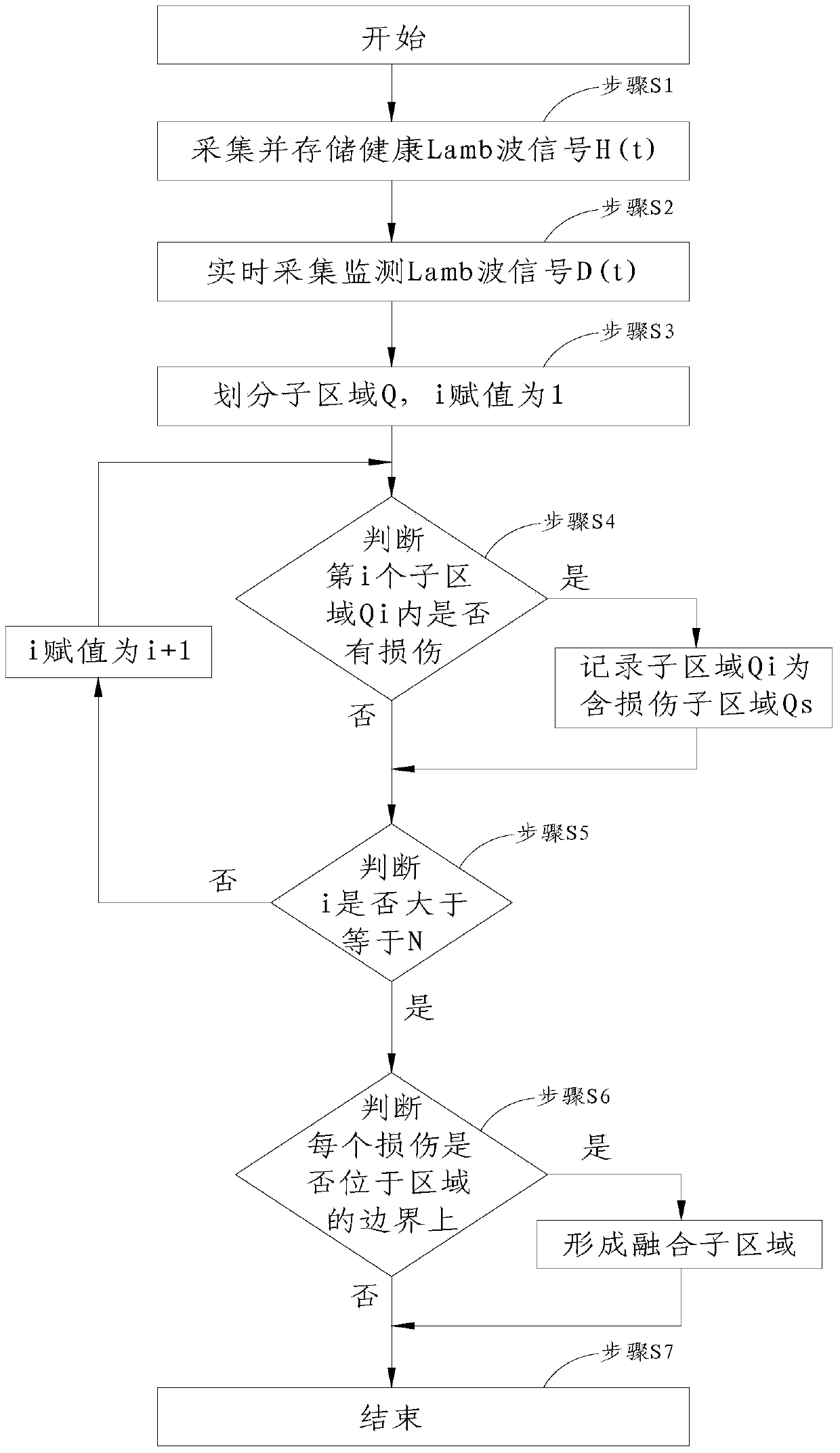
[0047] This preferred embodiment provides a damage monitoring method for a composite material plate structure based on piezoelectric elements and Lamb waves. This method uses the damage factor method to pre-judge the damage position of the composite material plate structure to be monitored, and then images the area where the damage is predicted to determine the exact position of the damage.

[0048] Because there is no need to image the non-damaged area, a lot of monitoring time is saved, and the efficiency is higher and the accuracy is higher.

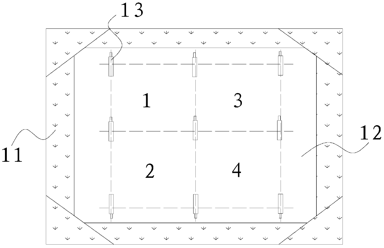
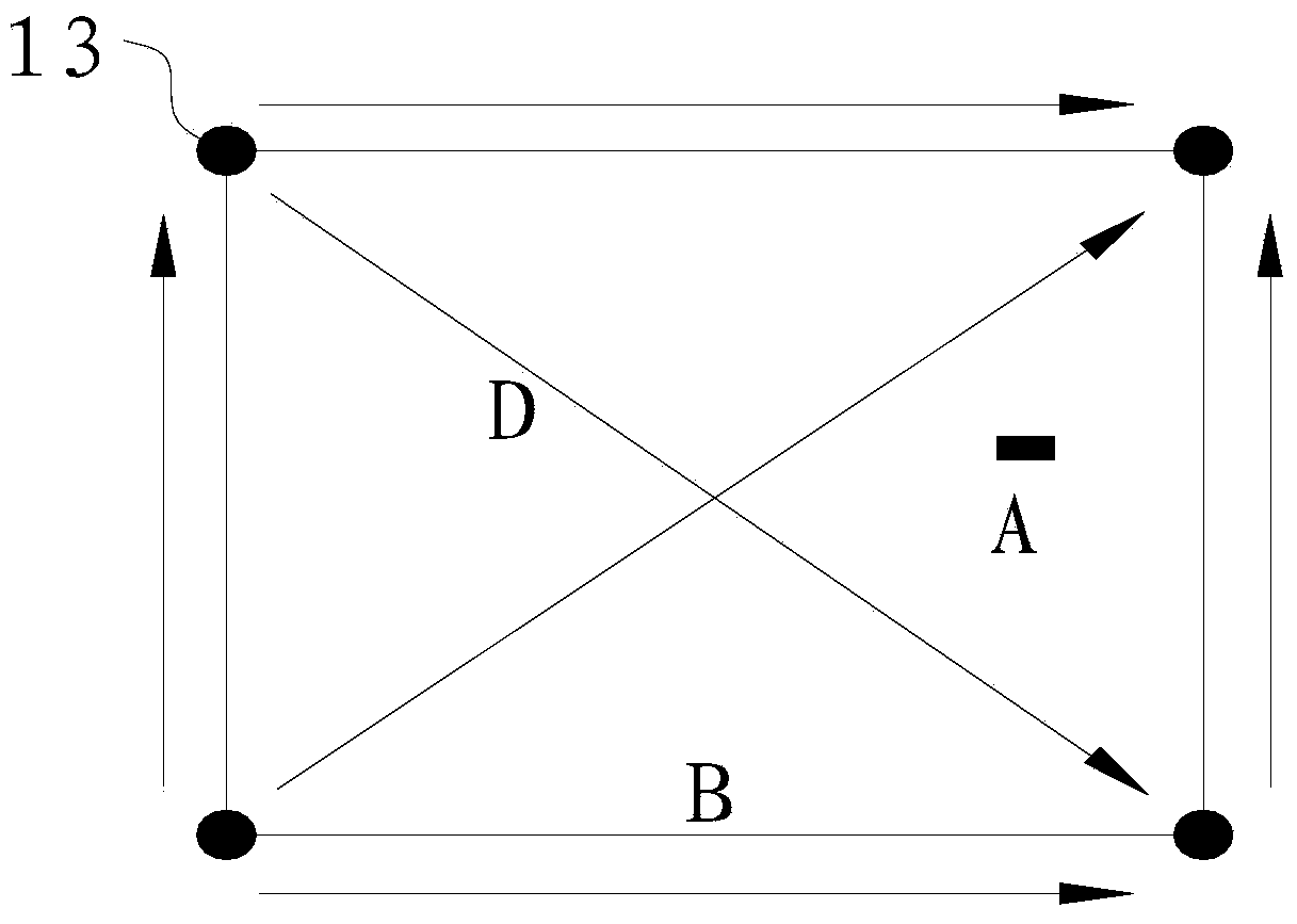
[0049] Such as figure 1 As shown, the method is to fix the composite material board 12 to be monitored on the monitoring device table 11 , and fix multiple piezoelectric elements 13 on the composite material board 12 . The piezoelectric elements 13 can be arranged in various shapes, preferably, a rectangular area is surrounded by four piezoelectric elements 13 . When the area of ​​the composite material plate 12 is large and there a...

Embodiment 2

[0087] This preferred embodiment provides a damage monitoring method for a composite material plate structure based on piezoelectric elements and Lamb waves. This method uses the damage factor method to pre-judge the damage position of the composite material plate structure to be monitored, and then images the area where the damage is predicted to determine the exact position of the damage.

[0088] The specific steps of the method are not limited, and it is only necessary to perform imaging on the area where the damage is predicted to determine the exact location of the damage; the selected damage factor and imaging method are not limited to the example given in the first preferred embodiment. Other damage factors and imaging methods are also available; when there are fewer subregions containing damage, it is not necessary to judge whether the subregion forms a fusion subregion with adjacent subregions.

[0089] Figure 12 It is the imaging diagram of this preferred embodime...


PUM


Abstract

The invention discloses a composite material plate structure damage monitoring method, and belongs to the technical field of composite material plate structure damage monitoring. The method is designed for solving the problems of low efficiency, low precision, and no simultaneous identification of many damages of present methods. The composite material plate structure damage monitoring method is a damage monitoring method based on a piezoelectric element and a Lamb wave. The method comprises the following steps: predetermining the damage position of a composite material plate structure to be monitored by using a damage factor technology, and imaging the area which is predetermined to be damaged in order to determine the accurate position of the damage. The composite material plate structure damage monitoring method can save a lot of monitoring time, improves the monitoring efficiency, can realize multi-damage positioning, and enhances the determination accuracy of the number and the position of the damages.

Description

technical field [0001] The invention relates to a damage monitoring method for a composite material plate structure. Background technique [0002] Composite material panels are widely used in aviation, aerospace, automotive and other engineering fields because of their advantages such as high specific strength, high specific stiffness, good fatigue resistance and designable material properties. However, the low interlaminar shear strength and tensile strength in the perpendicular plane direction make delamination damage prone to occur in composite panels. Delamination can result in a significant loss of compressive strength and stiffness, resulting in reduced load-carrying capacity. [0003] In order to identify and locate various damages in composite panels to predict structural life and perform structural maintenance, traditional methods such as percussion, ultrasound, X-rays, eddy current rays, potential measurements, and thermal stress fields are difficult to achieve. ...

Claims


Application Information

Patent Timeline
IPC IPC(8): G01N29/04G01N29/06G01N29/44
Inventor 卿新林高丽敏袁慎芳邱雷
Owner BEIJING AERONAUTIC SCI & TECH RES INST OF COMAC
Why Eureka
Try Eureka