
Special-shaped hole broach and machining process method thereof

A technology for special-shaped holes and round holes, which is applied to broaches, metal processing equipment, broaching machines, etc. It can solve problems such as failure to meet symmetry requirements, difficult to solve stress deformation, and poor processing and forming stability, so as to achieve good processing and forming stability. Effect

Inactive Publication Date: 2014-12-10
金华市红太阳工具厂
View PDF9 Cites 23 Cited by
  • Summary
  • Abstract
  • Description
  • Claims
  • Application Information

AI Technical Summary

Problems solved by technology

[0004] The present invention aims at broaches with special-shaped holes whose total length generally does not exceed 1100mm and whose slenderness ratio is lower than 48, which generally have large total length and high slenderness ratio in the prior art. , Poor processing and forming stability, etc., provide a special-shaped hole broach and its processing method with a total length of more than 1200mm and a slender ratio as high as 48-75, integral structure, high precision, good rigidity and excellent processing and forming stability.

Method used


Image

  • Special-shaped hole broach and machining process method thereof
  • Special-shaped hole broach and machining process method thereof
  • Special-shaped hole broach and machining process method thereof

Examples


Embodiment 1

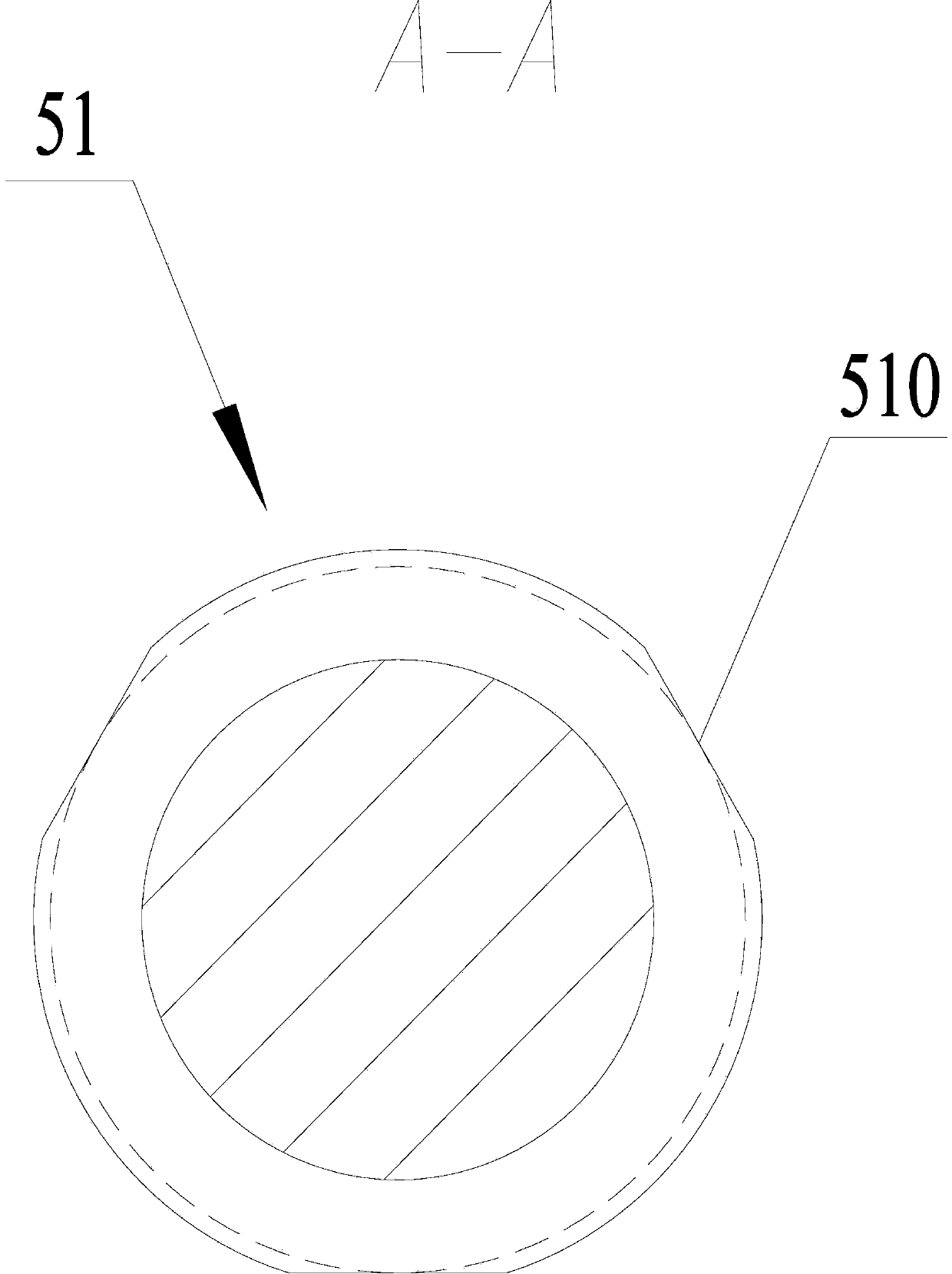
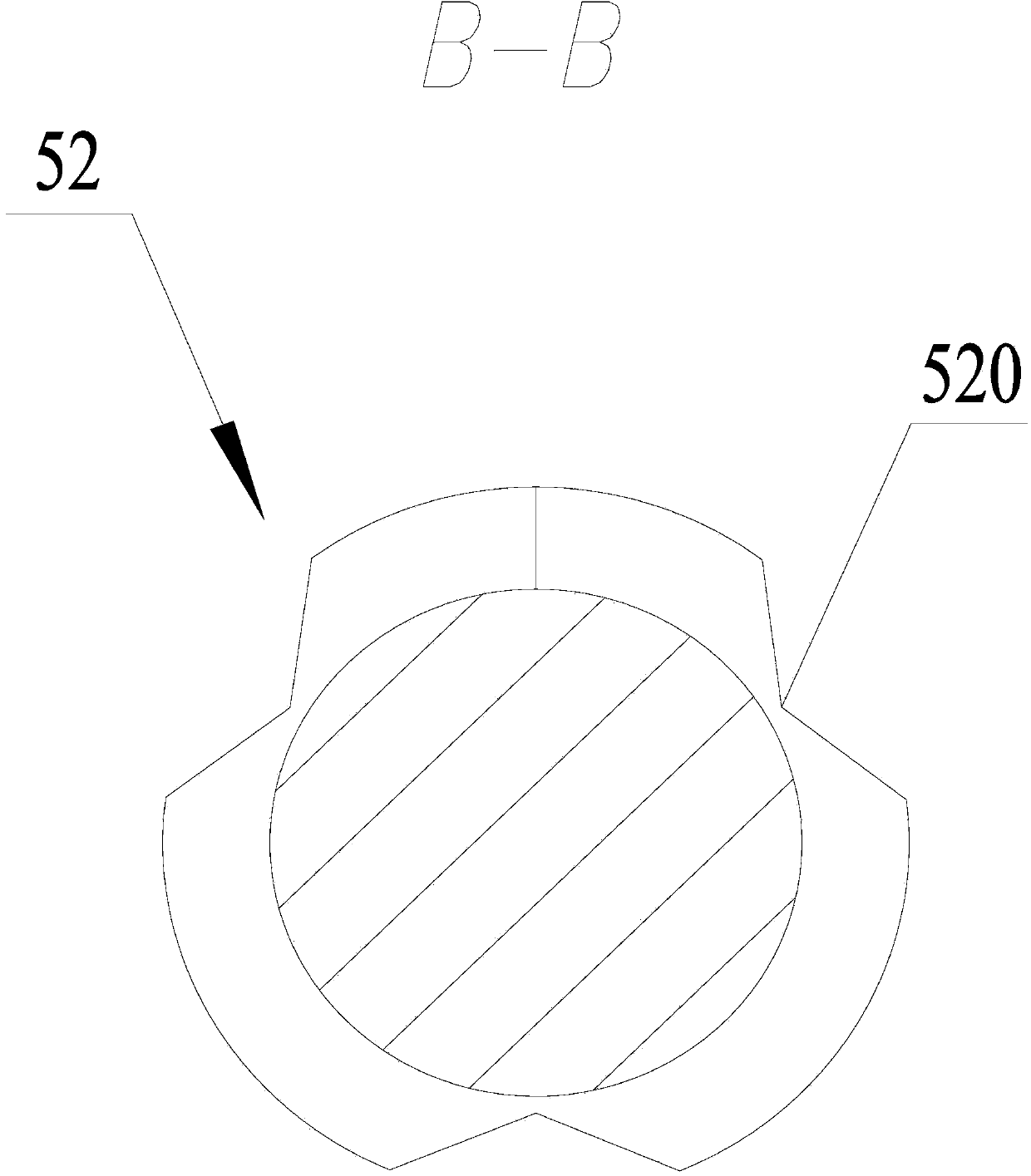
[0064] A special-shaped hole broach, such as Figure 1-6As shown, it includes a shank 1, a neck 2, a transition cone 3, a leading part 4, a cutting part 5 and a tail part 6, which are sequentially arranged and connected from the cutting end to the cutting end, and two adjacent cutting teeth 5 There is a chip flute 7 between them, the total length from the front end of the shank 1 to the end of the tail 6 is 1226mm, and the outer diameters from the leading part 4 to the tail 6 are in order from small to large; The integrated circular hole teeth 51, circular arc teeth 52, cutting teeth 53, transition teeth 54 and alignment teeth 55, the total number of teeth of the cutting part 5 is 130-150.

[0065] The outer diameter from the leading part 4 to the tail part 6 is 17-25 mm, and the ratio of the total length to the outer diameter is 48-75.

[0066] The total number of teeth of the cutting part 5 is 132, and the number of teeth of the circular hole teeth 51, circular arc teeth 52...


PUM

PropertyMeasurementUnit
Outer diameteraaaaaaaaaa

Abstract

The invention relates to a broach and discloses a special-shaped hole broach which comprises a handle part, a neck part, a transition conical part, a front guide part, cutting parts and a tail part. The handle part, the neck part, the transition conical part, the front guide part, the cutting parts and the tail part are sequentially connected into a whole from the cutting-in end to the cutting-out end. A scrap containing groove is formed between every two adjacent cutting teeth. The total length from the front end of the handle part to the tail end of the tail part is not smaller than 1200 mm, and the outer diameters from the front guide part to the tail part in sequence are sequentially increased; the cutting parts comprise round hole teeth, circular arc teeth, cutting teeth, transition teeth and calibration teeth, wherein the round hole teeth, the circular arc teeth, the cutting teeth, the transition teeth and the calibration teeth are sequentially arranged from front to back and connected into a whole. The number of the teeth of the cutting parts is from 130 to 150. The invention further discloses a machining process method for the special-shaped hole broach. The broach is large in total length and high in slenderness ratio; the multiple cutting parts different in tooth shape are used for broaching a special-shaped hole, based on the high-precision ultra-slenderness machining and thermal treating process, a method for carrying out segmentation gradual grinding through a locating sleeve and a supporting point is adopted, it is ensured that jump of the solid broach is from 0.01 mm to 0.02 mm, stress deformation caused by cutter relieving and drooping can be effectively avoided, and therefore the stability of machining and forming is good.

Description

technical field [0001] The invention relates to a broach, in particular to a special-shaped hole broach and a processing method thereof. Background technique [0002] With the transformation and development of industrial technology, broaches are more and more widely used in mass processing. The broach is a multi-tooth broaching tool, which is widely used in hole processing, and the processing of special-shaped holes is both the key point and the difficulty in hole processing technology. The high-precision ultra-slender broach is an excellent tool for processing special-shaped holes. [0003] High-precision ultra-slender broaches have very high requirements on precision and processing stability. At present, domestic high-precision ultra-slender broaches basically rely on imported products, but they are expensive and have a long delivery cycle, which is not conducive to the transformation and upgrading of domestic industrial technology. Existing broaches for special-shaped ...

Claims


Application Information

Patent Timeline
IPC IPC(8): B23D43/00B23P15/42
Inventor 洪军
Owner 金华市红太阳工具厂
Learn More