Gravity Self-Contained Welding Feed Mechanism
What is Al technical title?
Al technical title is built by PatSnap Al team. It summarizes the technical point description of the patent document.
A feeding mechanism, self-sufficient technology, applied in the field of machinery, can solve the problem of uneven feeding of copper materials, and achieve the effects of simple structure, uniformity, and easy manufacturing.
Active Publication Date: 2017-08-04
X E S IND JIANGSU CO LTD
View PDF14 Cites 0 Cited by
Summary
Abstract
Description
Claims
Application Information
AI Technical Summary
This helps you quickly interpret patents by identifying the three key elements:
Problems solved by technology
Method used
Benefits of technology
Problems solved by technology
[0003] Aiming at the problem of uneven feeding of copper materials in the existing brazing process of spectacle plates and cutting rings, the present invention provides a gravity self-supporting welding feeding mechanism
Method used
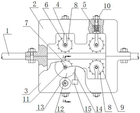
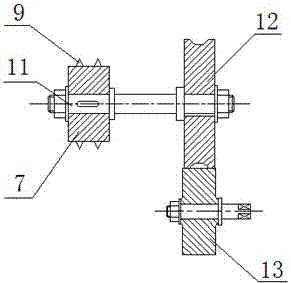
Image
Click on the blue label to locate the original text in one second.
Reading with bidirectional positioning of images and text.
Examples
Embodiment 1
[0018] Such as figure 1 , figure 2 As shown, the gravity self-supporting welding feed mechanism includes an upper frame 2, a lower frame 3, a telescopic shaft 4, a spring 5, a shaft 6, a driving wheel 7, a driven wheel 8, anti-skid teeth 9, a nut 10, a rotating shaft 11, and a pulley 12. Friction wheels 13, ropes 14, weights 15, the upper frame 2 and the lower frame 3 are provided with rectangular grooves, and through holes are arranged in the rectangular grooves, and the telescopic shaft 4 passes through the upper Frame 2 or the through hole of the rectangular groove of lower frame 3, one end of which is connected to driven wheel 8 through shaft 6, and the other end is matched with nut 10, and described spring 5 is arranged at the collar of telescopic shaft 4, so The two ends of the rotating shaft 11 are respectively equipped with a drive wheel 7 and a pulley 12, the rotating shaft 11 is assembled on the upper frame 2 or the lower frame 3, and the rope 14 is wound in the ou...
PUM
Abstract
The invention discloses a gravity self-feed welding feeding mechanism, and belongs to the field of machines. The gravity self-feed welding feeding mechanism comprises an upper rack, a lower rack, telescopic shafts, springs, shafts, a driving wheel, a driven wheel, anti-slipping teeth, nuts, a rotating shaft, a pulley, a friction wheel, a rope and a weight. The upper rack and the lower rack are provided with rectangular grooves respectively, through holes are formed in each rectangular groove, the telescopic shafts penetrate through the through holes of the rectangular groove in the upper rack or the rectangular groove in the lower rack, one ends of the telescopic shafts are connected with the driven wheel, the other ends of the telescopic shafts are matched with the nuts, the two ends of the rotating shaft are provided with the driving wheel and the pulley respectively, the rotating shaft is assembled on the upper rack or the lower rack, the rope is wound in a groove in the outer edge of the pulley, and the weight is connected with the tail end of the rope. The problem that a copper material is fed unevenly in the existing copper brazing process of a wear plate and a cutting ring is solved, and the gravity self-feed welding feeding mechanism has the advantages of being simple in structure, reasonable in design and easy to manufacture.
Description
technical field [0001] The invention belongs to the field of machinery, and more specifically relates to a copper feeding mechanism used for welding. Background technique [0002] Spectacle plates and cutting rings are important parts in concrete pump trucks. Because they are subjected to high pressure and frequent friction during work, they become vulnerable parts in concrete pump trucks. In order to reduce the wear of spectacle plates and cutting rings during work, a layer of metal alloy is often embedded on the surface, and before welding the metal alloy, a uniform layer of copper is generally welded on the surface, and then on the basis of copper Inlaid carbide. However, in the welding of copper on the surface of spectacle plates and cutting rings, the problem of uneven thickness of copper welding often occurs. At present, the feeding of copper materials is mostly delivered by hand, which has a certain degree of randomness, and when operated manually, the distance from...
Claims
Application Information
Patent Timeline
Application Date:The date an application was filed.
Publication Date:The date a patent or application was officially published.
First Publication Date:The earliest publication date of a patent with the same application number.
Issue Date:Publication date of the patent grant document.
PCT Entry Date:The Entry date of PCT National Phase.
Estimated Expiry Date:The statutory expiry date of a patent right according to the Patent Law, and it is the longest term of protection that the patent right can achieve without the termination of the patent right due to other reasons(Term extension factor has been taken into account ).
Invalid Date:Actual expiry date is based on effective date or publication date of legal transaction data of invalid patent.