Injection molding machine and injection molding method adopting injection molding machine

An injection molding machine and an inert gas technology, which is applied in the field of injection molding machines to avoid yellowing of the light guide plate during the production process, can solve the problems of insignificant improvement effect and increased cost, and achieves the solution of the yellowing of the light guide plate and the high reliability. , the effect of low cost

Inactive Publication Date: 2014-12-10
BOE OPTICAL SCI & TECH +1
View PDF4 Cites 7 Cited by
  • Summary
  • Abstract
  • Description
  • Claims
  • Application Information

AI Technical Summary

Problems solved by technology

At present, high flow materials are used to overcome the problem that this method not only increases the cost, but also does not improve the effect obviously

Method used


Image

  • Injection molding machine and injection molding method adopting injection molding machine
  • Injection molding machine and injection molding method adopting injection molding machine
  • Injection molding machine and injection molding method adopting injection molding machine

Examples


Embodiment 1

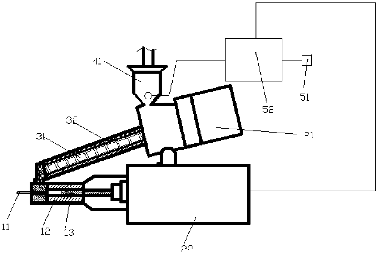
[0038] Such as figure 1 As shown, the inert gas generator in the first embodiment includes a nitrogen generator 52, one end of the nitrogen generator 52 is connected to the hopper 41, and the other end is connected to the driving device. The driving device controls the nitrogen generator 52 to be turned on to generate nitrogen, and the nitrogen generator 52 is connected with an air compressor 51 . The air is collected by the air compressor 51 and then the compressed gas produced is sent to the nitrogen generator 52 through the pipeline.

[0039] Such as Figure 4 As shown, the specific steps of using the injection molding machine provided in this embodiment to inject a non-yellowing light guide plate are as follows:

[0040] S1, the nitrogen generator 52 replaces the oxygen in the hopper 41 with nitrogen;

[0041] S2. After the oxygen in the hopper 41 is replaced by nitrogen, the screw 31 rotates to add materials to the barrel 32;

[0042]S3. The driving device drives the ...

Embodiment 2

[0045] The structure of the injection molding machine provided in the second embodiment is basically the same as that in the first embodiment, and the similarities will not be repeated. The difference lies in the inert gas generator.

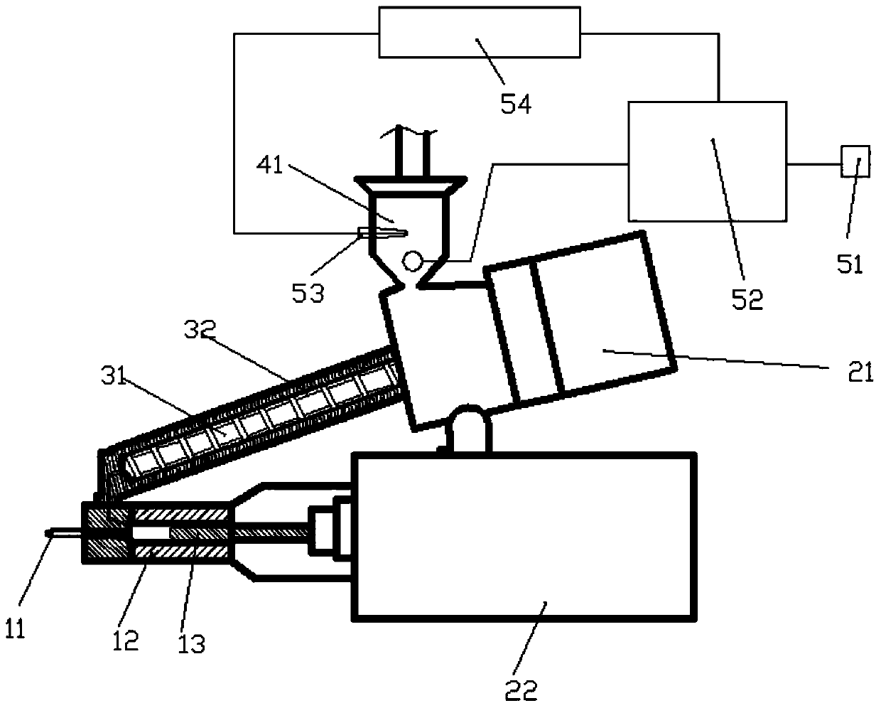
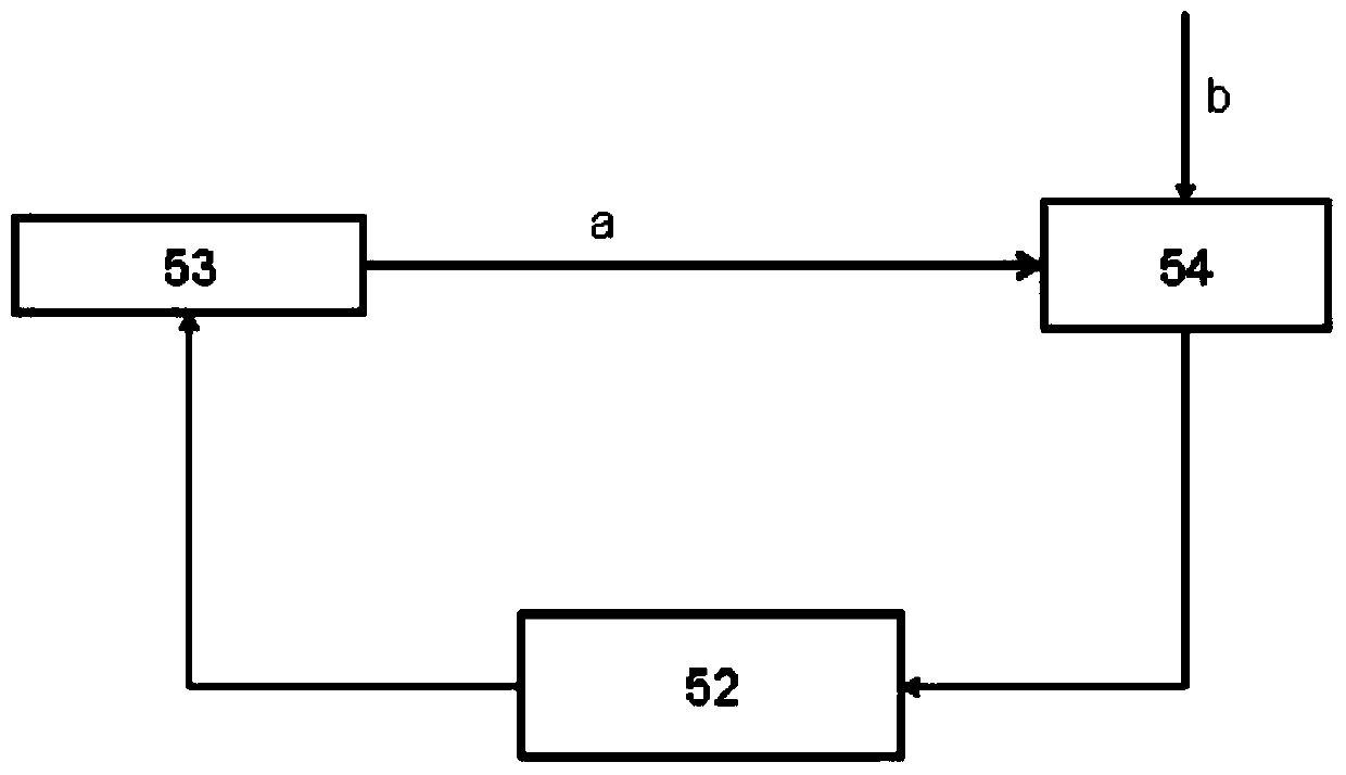
[0046] Such as figure 2 As shown, the inert gas generating device in the injection molding machine provided in the second embodiment includes a nitrogen generator 52, a detection probe 53 and a signal controller 54, the detection probe 53 is arranged in the hopper 41, and the detection probe 53 is electrically connected to the signal controller 54 , the signal controller 54 controls the opening and closing of the inert gas generator. The detection probe 53 is used to detect the oxygen in the hopper 41, and gives different signals according to the oxygen content, and transmits the signal to the signal controller 54 to analyze the received signal. When the oxygen content exceeds the set value, the signal is given. The signal induced by the nitro...


PUM


Abstract

The invention relates to the technical field of liquid crystal display, and discloses an injection molding machine. The injection molding machine comprises a hopper used for placing a material, and an inert gas generating device connected with the hopper, wherein the inert gas generating device is used for feeding an inert gas in the hopper. According to the injection molding machine provided by the invention, plasticizing of the material is completed under the protection of nitrogen, the problem of yellowing of a light guide plate due to oxygenolysis of the material is effectively solved; the injection molding machine has the characteristics of being low in cost, easy to implement and high in reliability.

Description

technical field [0001] The invention relates to the field of liquid crystal display technology, in particular to an injection molding machine and an injection molding method using the injection molding machine, in particular to an injection molding machine capable of avoiding yellowing of a light guide plate in the production process and an injection molding method using the injection molding machine method. Background technique [0002] The lightweight and ultra-thin development trend of smart phones and tablet computers puts forward higher requirements for the thinning of display module devices. At present, apart from a few high-end mobile devices using OLED (English name: Organic Light-Emitting Diode, Chinese name: Organic Light-Emitting Diode) display to achieve ultra-thin, more brand manufacturers choose LCD (English name: Liquid Crystal Display , Chinese name: liquid crystal display) screen. Since the LCD screen itself does not emit light, the clear display of the pi...

Claims


Application Information

Patent Timeline
Patent Type & Authority Applications(China)
IPC IPC(8): B29C45/76B29C45/17B29C45/54
CPCB29C45/1701B29C45/18B29C45/53B29C2045/1875B29L2011/0075B29C45/0025
Inventor 董文奇李虎陈明发
Owner BOE OPTICAL SCI & TECH
Why Eureka
Try Eureka