A lime digestion steam treatment device

A technology of processing device and steam, applied in chemical instruments and methods, separation of dispersed particles, use of liquid separating agent, etc., can solve the problems of jumping into lime discharge device, polluting the surrounding environment, caking and blocking of discharge device, etc.

Active Publication Date: 2016-01-27
WUXI XUELANG ENVIRONMENTAL TECH CO LTD
View PDF4 Cites 0 Cited by
  • Summary
  • Abstract
  • Description
  • Claims
  • Application Information

AI Technical Summary

Problems solved by technology

[0002] At present, a variety of absorbents are used in the flue gas treatment process of waste incineration power plants to absorb harmful gases in the flue gas after waste incineration. Among them, lime is widely used. In order to improve the utilization efficiency and deacidification efficiency of lime, it is usually necessary to Mature lime prepared from quicklime is diluted to a certain concentration and sprayed into the reaction tower to chemically react with harmful acidic gases in the flue gas to achieve the purpose of treating acidic and harmful gases in the flue gas; quicklime is an exothermic reaction during the digestion process, so in this A large amount of water vapor will be generated during the process, and the water vapor will flow back into the unloading equipment from the quicklime feeding port, blocking the equipment and affecting the normal digestion of quicklime
In the traditional quicklime digestion, a large exhaust pipe is installed on the lime digestion tank, and the steam is discharged through the natural lift of the steam. Because the digestion pipe is under a slight positive pressure, a small amount of water vapor will still flow into the lime discharge device , causing the unloading device to agglomerate and block, and the steam discharged through the exhaust pipe contains a certain amount of dust, which also seriously pollutes the surrounding environment

Method used


Image

  • A lime digestion steam treatment device
  • A lime digestion steam treatment device
  • A lime digestion steam treatment device

Examples


Embodiment Construction

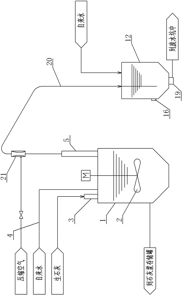
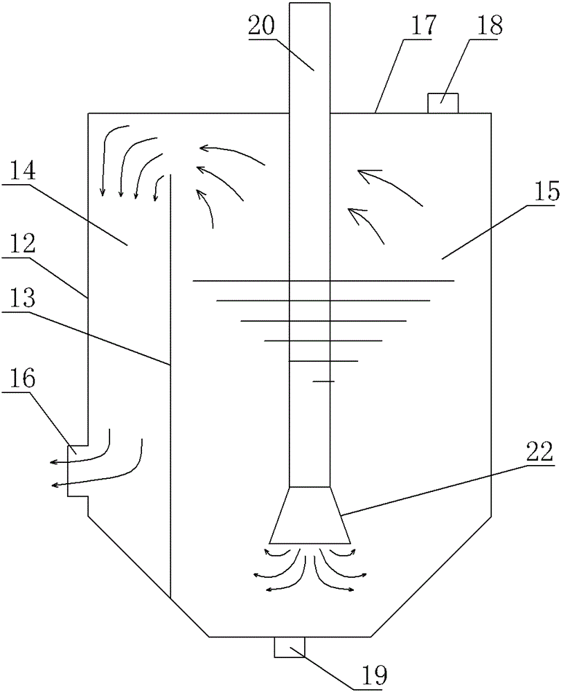
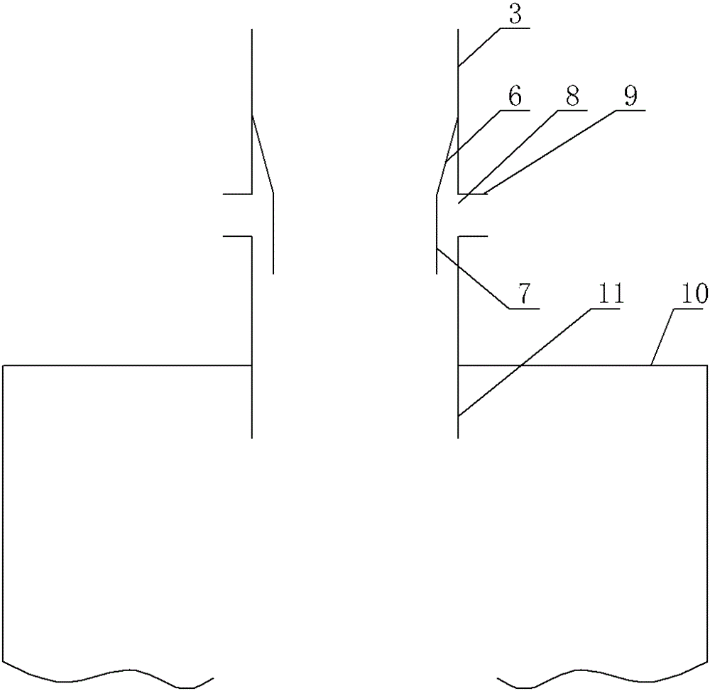
[0016] A lime digestion steam treatment device, see Figure 1 ~ Figure 3 : It comprises a quicklime digestion tank 1, a stirrer 2 is arranged in the quicklime digestion tank 1, a feed pipe 3, a water inlet pipe 4, and a steam exhaust pipe 5 are respectively arranged on the quicklime digestion tank 1, and the bottom of the quicklime digestion tank 1 is provided with The outlet is connected to the lime slurry storage tank. The middle part of the inner cavity of the feed pipe 3 is provided with ash guide pipe structure 6 closed from top to bottom. The lower part of the ash guide pipe structure 6 can also be a cylindrical guide structure 7. The outer wall of the corresponding feed pipe 3 is provided with an air supply hole 8, and the external air supply pipe 9 is connected to the air supply hole 8, and the gas in the air supply hole 8 that passes into the feed pipe 4 goes downward along the outer wall of the guide pipe structure 6 flow, the bottom of the feed pipe 3 extends downwa...


PUM


Abstract

The invention provides a lime slaking steam treatment device. According to the device, steam in a slaking tank can be smoothly discharged, so that the steam does not enter a lime discharging device, smooth discharging of the lime discharging device is ensured, the discharged steam is purified and discharged into an ambient environment, and environment friendliness is ensured. The lime slaking steam treatment device comprises a quick lime slaking tank, wherein a stirrer is arranged in the quick lime slaking tank; a feeding pipe, a water inlet pipe and a steam exhaust smoke pipe are respectively arranged on the quick lime slaking tank; and an outlet is formed in the bottom of the quick lime slaking tank and is communicated with a lime slurry storage tank. The lime slaking steam treatment device is characterized in that a lime guide tube structure which is closed up from top to bottom is formed in the middle of an inner cavity of the feeding pipe; an air supply hole is formed in an outer wall of the feeding pipe corresponding to the lime guide tube structure; an external air supply pipe is communicated with the air supply hole; the lime slaking steam treatment device further comprises a smoke washing tank which is of a closed structure; and the steam exhaust smoke pipe is communicated with the bottom of the smoke washing tank by virtue of an air delivery pipeline.

Description

technical field [0001] The invention relates to the technical field of waste incineration power generation flue gas treatment structure, in particular to a lime digestion steam treatment device. Background technique [0002] At present, a variety of absorbents are used in the flue gas treatment process of waste incineration power plants to absorb harmful gases in the flue gas after waste incineration. Among them, lime is widely used. In order to improve the utilization efficiency and deacidification efficiency of lime, it is usually necessary to Mature lime prepared from quicklime is diluted to a certain concentration and sprayed into the reaction tower to chemically react with harmful acidic gases in the flue gas to achieve the purpose of treating acidic and harmful gases in the flue gas; quicklime is an exothermic reaction during the digestion process, so in this A large amount of water vapor will be generated during the process, and the water vapor will flow back into the...

Claims


Application Information

Patent Timeline
Patent Type & Authority Patents(China)
IPC IPC(8): C04B2/08B01D47/02
Inventor 虞大青
Owner WUXI XUELANG ENVIRONMENTAL TECH CO LTD
Why Eureka
Try Eureka