Construction technology for prefabricating a corrugated steel web PC I beam into combined box girder bridge

A technology of corrugated steel webs and construction technology, which is applied to bridges, bridge materials, bridge construction, etc., can solve the problems of long construction period, immaturity, and high cost of manpower and material resources, and achieve low input costs, simple structure, and easy construction. convenient effect

Active Publication Date: 2014-12-10
中铁二十局集团第五工程有限公司
View PDF8 Cites 20 Cited by
  • Summary
  • Abstract
  • Description
  • Claims
  • Application Information

AI Technical Summary

Problems solved by technology

However, the prefabrication technology of prestressed concrete composite beams with corrugated steel webs is not yet mature enough. , The number of webs is large, especially with the continuous increase of the span of prefabricated beams, the prefabricated construction is very difficult, and the quality of prefabricated beams is not easy to guarantee
In addition, when the prefabricated installation construction method is used for construction, there are still problems such as complex construction technology, long construction period, high manpower and material input costs, and difficulty in guaranteeing construction quality.
Therefore, there is a lack of a prefabricated corrugated steel web PC I-beam to composite box girder bridge construction technology with simple process steps, reasonable design, convenient implementation, short construction period, and high construction quality, using prefabricated pedestals and positioning brackets Complete the prefabrication of the girder body and effectively ensure the construction quality of the constructed composite box girder bridge

Method used


Image

  • Construction technology for prefabricating a corrugated steel web PC I beam into combined box girder bridge
  • Construction technology for prefabricating a corrugated steel web PC I beam into combined box girder bridge
  • Construction technology for prefabricating a corrugated steel web PC I beam into combined box girder bridge

Examples


Embodiment Construction

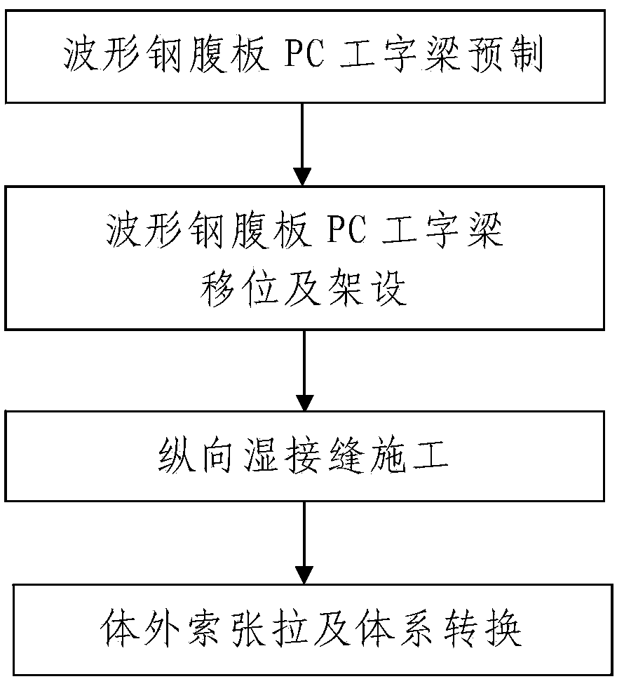
[0069] Such as figure 1 A construction process of prefabricated corrugated steel web PC I-beam to composite box girder bridge is shown. The composite box girder bridge constructed includes a composite box girder erected on the lower support system of the bridge. The direction is divided into a plurality of composite box girder segments, each of which is formed by connecting two PC I-beams 7 with corrugated steel webs arranged symmetrically. The process includes the following steps:

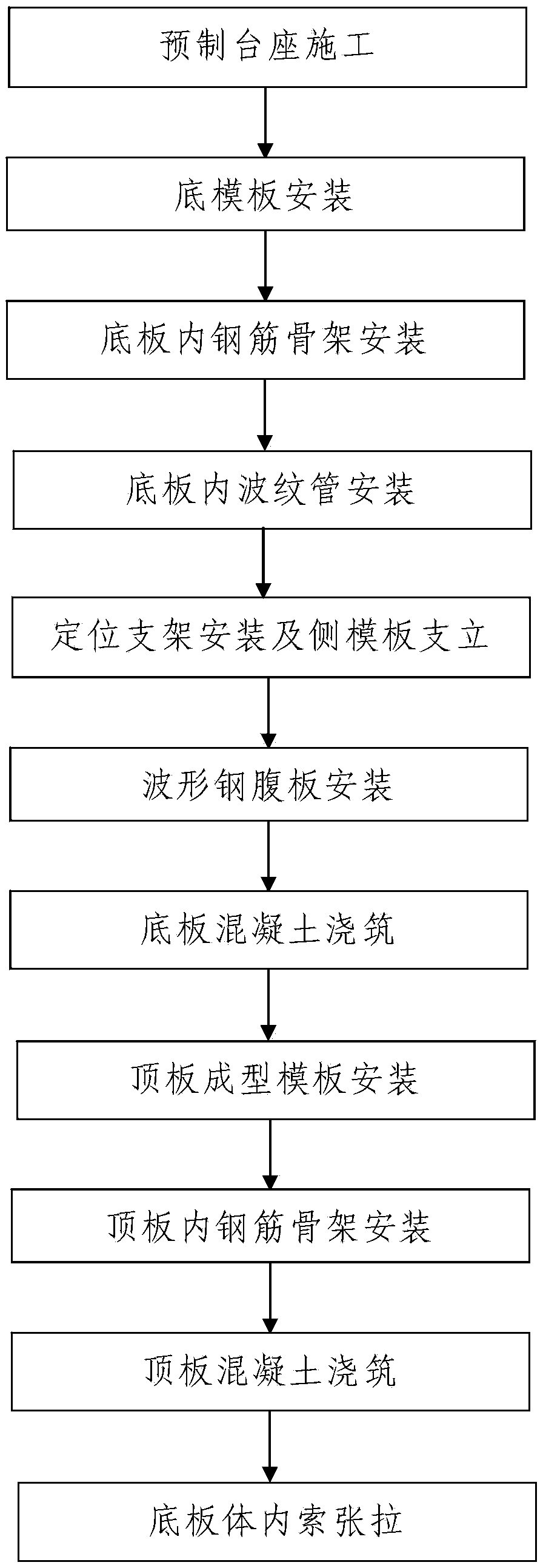
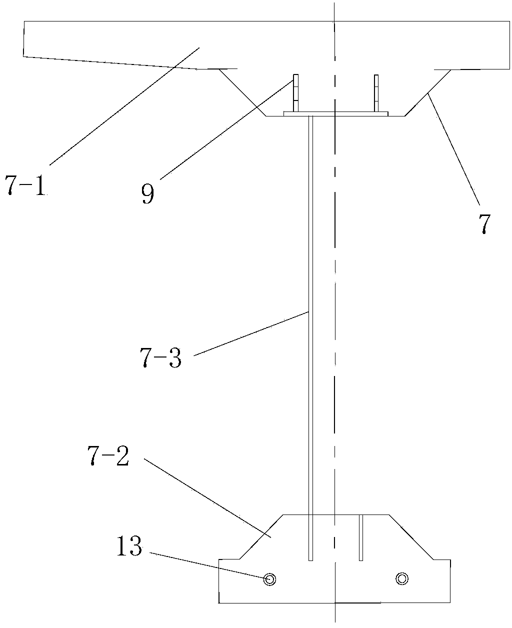
[0070] Step 1. Prefabrication of PC I-beams with corrugated steel webs: combination Picture 1-1 , the corrugated steel web PC I-beam 7 required for the construction of the composite box girder is prefabricated, and the process is as follows:

[0071] Step 101, construction of prefabricated pedestal: first lay a layer of concrete cushion 5 on the prefabricated site, and construct concrete pedestal 1 on the concrete cushion 5 as a prefabricated pedestal for corrugated steel web PC I-beam 7, see ...


PUM


Abstract

The invention discloses a construction technology for prefabricating a corrugated steel web PC I beam into a combined box girder bridge. Each combined box girder segment in a combined box girder of the combined box girder bridge is formed by connecting two corrugated steel web PC I beams. The construction technology comprises the following steps: Step I, prefabricating the corrugated steel web PC I beams: pedestal prefabricating construction, installation of a soffit formwork, installation of a reinforcement cage in a bottom plate, installation of a corrugated pipe in the bottom plate, installation of a positioning bracket and erection of a side formwork, installation of a corrugated steel web, pouring of concrete on the bottom plate, installation of a top plate molding template, installation of the reinforcement cage in a top plate, pouring of concrete on the top plate, and stretch-drawing of a cable in the bottom plate; Step II, displacement and erection of the corrugated steel web PC I beams; Step III, lengthways wet joint construction; Step IV, stretch-drawing of a cable out of the bottom plate and system conversion. According to the invention, the processing steps are simple, the design is reasonable, the implementation is convenient, the construction period is short, the construction quality is high, pedestal prefabricating and the positioning bracket are combined to complete bridge prefabrication, and the construction quality of the combined box girder bridge can be effectively ensured.

Description

technical field [0001] The invention belongs to the technical field of bridge construction, and in particular relates to a construction process of a prefabricated corrugated steel web PC I-beam-turned-combined box-girder bridge. Background technique [0002] In order to meet the needs of economic construction and social development, the development of modern concrete bridges has put forward the goal of "light weight, high strength, and long span". Box girders can meet the stability requirements of the construction process due to their large bending and torsional rigidity. Analyzing the composition of the box girder, it can be known that the thickness of the top and bottom plates of the box girder is determined according to the bending resistance requirements of the section, and is restricted by the force of the structure and construction performance. The weight can be reduced by reducing the thickness of the top and bottom plates , the potential to reduce the cost is very li...

Claims


Application Information

Patent Timeline
Patent Type & Authority Applications(China)
IPC IPC(8): E01D21/00E01D2/04E01D101/28
Inventor 王生兵庞东升张伯平黄聪聪王婷婷张云飞李兴刘广庆
Owner 中铁二十局集团第五工程有限公司
Why Eureka
Try Eureka