Continuous sounding pipe installation method and device for detecting concrete filling pile

An acoustic tube, uninterrupted technology, applied in the testing of infrastructure, construction, infrastructure engineering and other directions, can solve problems such as increased labor costs, great construction period pressure, material waste, etc., to reduce construction costs and improve work efficiency. , the effect of improving economic efficiency

Inactive Publication Date: 2014-12-10
陈默
View PDF5 Cites 7 Cited by
  • Summary
  • Abstract
  • Description
  • Claims
  • Application Information

AI Technical Summary

Problems solved by technology

[0006] Although this method has been used until now, it has been found that there are two obvious defects in construction practice: one is the construction of pipe plugging, and the other is waste of materials
[0015] In short, the traditional method of laying acoustic tubes not only results in increased labor costs and great pressure on the construction period, but also causes serious waste of materials. Under the requirements of the principles of energy saving, economy, and high efficiency, it is urgent to find a method that will not cause plugging. The acoustic tube embedding method that can save a lot of steel, that is, the acoustic wave transmission method to detect the concrete pouring pile without interruption acoustic tube installation method

Method used


Image

  • Continuous sounding pipe installation method and device for detecting concrete filling pile
  • Continuous sounding pipe installation method and device for detecting concrete filling pile
  • Continuous sounding pipe installation method and device for detecting concrete filling pile

Examples


Embodiment

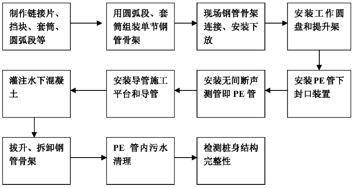
[0036] First, the material selection of the continuous acoustic tube

[0037]For the sound wave transmission method, the uninterrupted sound measuring tube should choose PE round tube (polyethylene resin) and give up the steel tube. The size of the PE pipe is φ40 and the thickness is 3mm. Reasons for choosing PE pipe: PE pipe has good sound permeability and high strength, and the circular pipe has a large ability to resist lateral pressure, which can meet the lateral pressure of concrete at the bottom of the cast-in-situ pile; PE pipe has good toughness, and the finished product can be rolled into a disc, and the unfolded length is several From ten meters to hundreds of meters, one-time ruling can be made according to the working length, which is also the main reason to ensure the uninterrupted sound pipe; the price of PE pipe is low, which is 25% of the current price of $57×3 steel pipe.

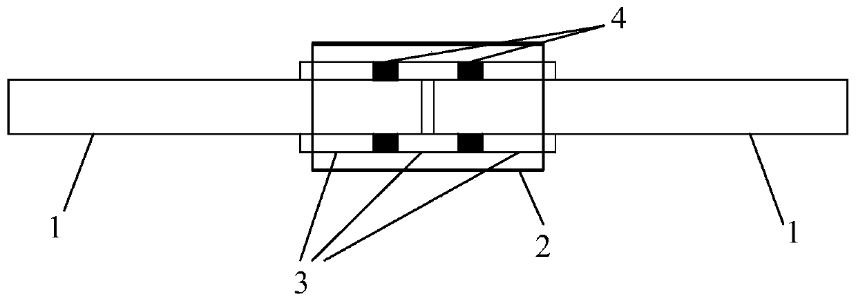
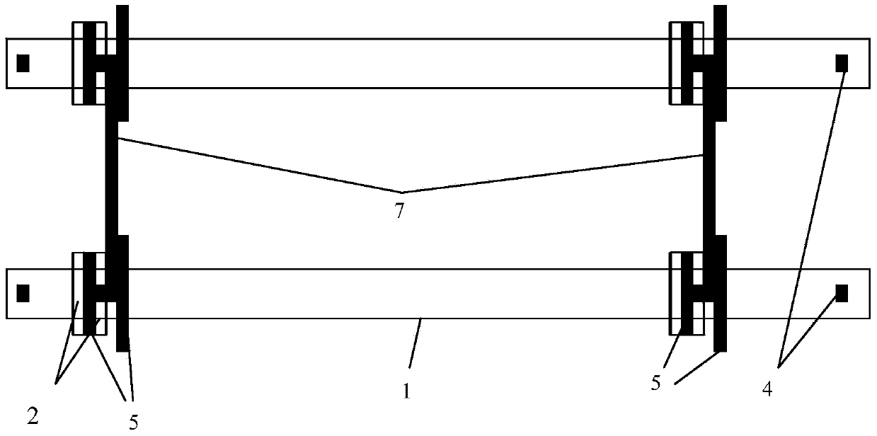
[0038] 2. Fabrication of uninterrupted acoustic tube skeleton

[0039] Since PE pipes...


PUM


Abstract

The invention discloses a continuous sounding pipe installation method for detecting a concrete filling pile through an acoustic transmission method. The method comprises the steps that firstly, a steel pipe framework is put to the bottom of the pile axuilairily; a continuous sounding pipe is installed at one time through a sounding pipe passage formed by the installed steel pipe framework, and the bottom of the pipe is sealed when the continuous sounding pipe is put to the bottom of the pile; concrete is injected, the steel pipe framework is pulled out section by section in the injecting process, and the continuous sounding pipe is left in concrete to become a passage to defect the completeness of a pile body structure through the acoustic transmission method; the completeness of the pile body structure is detected through the acoustic transmission method. The continuous sounding pipe installation method and device for detecting the concrete filling pile largely improve work efficiency, save a large number of steel materials, reduce the construction cost, improve economic benefits and have great application prospects in pile foundation construction of railways, highways, airports and the like.

Description

technical field [0001] The invention belongs to the technical field of building pile foundation construction, in particular to a method for installing an uninterrupted acoustic measuring tube for detecting concrete pouring piles by means of acoustic wave transmission. Background technique [0002] Concrete pouring pile foundation has been widely used in the construction of bridge substructure and building foundation since the last century. Among the various non-destructive testing methods for the quality of cast-in-situ piles and the structural integrity of the pile body, the acoustic transmission method is widely used in bridge foundations in various industries such as railways, highways, and housing construction because of its advantages such as accurate judgment, convenient detection, and insusceptibility to external influences. Pile detection is commonly used. JTG / TF81-01-2004 "Technical Regulations for Dynamic Measurement of Highway Engineering Pile" stipulates that th...

Claims


Application Information

Patent Timeline
Patent Type & Authority Applications(China)
IPC IPC(8): E02D33/00
Inventor 陈默
Owner 陈默
Why Eureka
Try Eureka